EBK STRUCTURAL ANALYSIS
5th Edition
ISBN: 9780100469105
Author: KASSIMALI
Publisher: YUZU
Question
Book Icon
Chapter D, Problem 10P
To determine

Calculate the reactions for the given beam.

Sketch the shear and bending moment diagrams for the given beam.

Expert Solution & Answer
Check Mark

Answer to Problem 10P

The horizontal reaction at A is Ax=0_.

The vertical reaction at A is Ay=45.88kN_.

The vertical reaction at C is Cy=100.5kN_.

The vertical reaction at E is Ey=198.3kN_.

The vertical reaction at G is Gy=45.32kN_.

Explanation of Solution

Given information:

The structure is given in the Figure.

The settlement of support A is 10 mm, support C is 65 mm, support E is 40 mm, and support G is 25 mm.

Apply the sign conventions for calculating reactions using the three equations of equilibrium as shown below.

  • For summation of forces along x-direction is equal to zero (Fx=0), consider the forces acting towards right side as positive (+) and the forces acting towards left side as negative ().
  • For summation of forces along y-direction is equal to zero (Fy=0), consider the upward force as positive (+) and the downward force as negative ().
  • For summation of moment about a point is equal to zero (Matapoint=0), consider the clockwise moment as negative and the counter clockwise moment as positive.

Calculation:

Find the degree of indeterminacy of the structure:

Degree of determinacy of the beam is equal to the number of unknown reactions minus the number of equilibrium equations.

The beam is supported by 5 support reactions and the number of equilibrium equations is 3.

Therefore, the degree of indeterminacy of the beam is i=2.

Select the bending moment MC and ME at the interior supports C and E as redundant.

Consider the supports A, C, and E as l, c, and r respectively.

Express the general three-moment equation as shown below:

MlLlIl+2Mc(LlIl+LrIr)+MrLrIr=[PlLl2klIl(1kl2)PrLr2krIr(1kr2)wlLl34IlwrLr34Ir6E(ΔlΔcLl+ΔrΔcLr)]        (1)

Here, Mc is the bending moment at support c, Ml,Mr are the bending moments at the adjacent supports to the left and to the right of c, E is the modulus of elasticity, Ll,Lr are the lengths of the spans to the left and to the right of c, Il,Ir are the moments of inertia of the spans to the left and to the right of c, Pl,Pr are the concentrated loads acting on the left and the right spans, kl or kr is the ratio of distance of Pl or Pr from the left or right support to the span length, wl,wr are the uniformly distributed loads to the left and right spans, Δc is the settlement of support c, Δl,Δr is the settlement of adjacent supports to the left and to the right of c,

The settlement of support A is 0.01 m, support C is 0.065 m, support E is 0.04 mm, and support G is 0.025 m.

Apply three-moment equation at joint C,

The moment at A is MA=0.

Substitute 10 m for Ll, 10 m for Lr I for Il, 2I for Ir, 120 kN for Pl, 120 kN for Pr, 0.6 for kl, 0.4 for kr, 0 for wl, 0 for wr, 0.01 m for Δl, 0.065 m for Δc, and 0.04 m for Δr in Equation (1).

0+2MC(10I+102I)+ME(102I)=[120(10)2(0.6)I(10.62)120(10)2(0.4)2I(10.42)6E(0.010.06510+0.040.06510)]30MCI+5MEI=4,608I2,016I+0.048E30MC+5ME=6,624+0.048EI

Substitute 200 GPa for E and 500(106)mm4 for I.

30MC+5ME=6,624+0.048(200GPa)(500(106)mm4)30MC+5ME=[6,624+0.048(200GPa×106kN/m21GPa)×(500(106)mm4×1012m41mm4)]30MC+5ME=6,624+4,80030MC+5ME=1,824        (2)

Apply three-moment equation at joint E,

The moment at G is MG=0.

Substitute 10 m for Ll, 8 m for Lr 2I for Il, I for Ir, 120 kN for Pl, 150 kN for Pr, 0.6 for kl, 0.5 for kr, 0 for wl, 0 for wr, 0.065 m for Δl, 0.04 m for Δc, and 0.025 m for Δr in Equation (1).

MC(102I)+2ME(102I+8I)=[120(10)2(0.6)2I(10.62)150(8)2(0.5)I(10.52)6E(0.0650.0410+0.0250.048)]5MCI+26MEI=2,304I3,600I0.00375E5MC+26ME=5,9040.00375EI

Substitute 200 GPa for E and 500(106)mm4 for I.

5MC+26ME=5,9040.00375(200GPa)(500(106)mm4)5MC+26ME=[5,9040.00375(200GPa×106kN/m21GPa)×(500(106)mm4×1012m41mm4)]5MC+26ME=5,9043755MC+26ME=6,279        (3)

Solve Equation (2) and Equation (3).

MC=21.2kNmME=237.4kNm

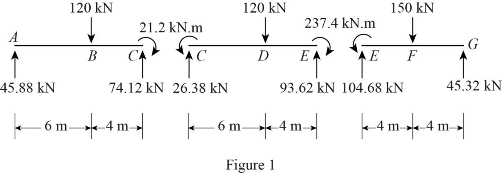
Sketch the span end moments and shears for span ABC, CDE, and EFG as shown in Figure 1.

EBK STRUCTURAL ANALYSIS, Chapter D, Problem 10P , additional homework tip  1

Use equilibrium equations:

For span ABC,

Summation of moments of all forces about A is equal to 0.

MA=0Cy(10)21.2120(6)=0Cy=74.12kN

Summation of forces along y-direction is equal to 0.

+Fy=0Ay120+Cy=0Ay120+74.12=0Ay=45.88kN

For span CDE,

Summation of moments of all forces about C is equal to 0.

MC=0Ey(10)+21.2237.4120(6)=0Ey=93.62kN

Summation of forces along y-direction is equal to 0.

+Fy=0Cy120+Ey=0Cy120+93.62=0Cy=26.38kN

For span EFG,

Summation of moments of all forces about E is equal to 0.

ME=0Gy(8)+237.4150(4)=0Gy=45.32kN

Summation of forces along y-direction is equal to 0.

+Fy=0Ey150+Gy=0Ey150+45.32=0Ey=104.68kN

Sketch the reactions for the given beam as shown in Figure 2.

EBK STRUCTURAL ANALYSIS, Chapter D, Problem 10P , additional homework tip  2

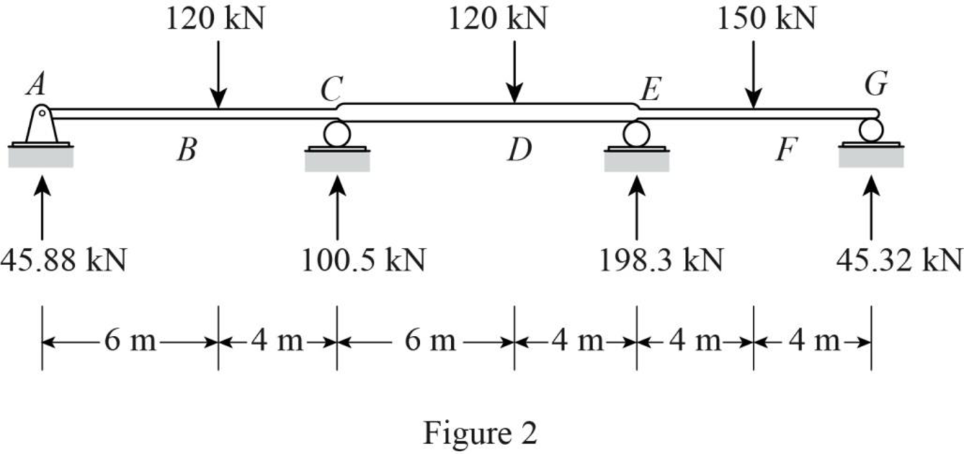
Find the shear force (S) for the given beam:

At point A,

SA=45.88kN

At point B,

SB,L=45.88kNSB,R=45.88120=74.12kN

At point C,

SC,L=45.88120=74.12kNSC,R=45.88120+100.5=26.38kN

At point D,

SD,L=45.88120+100.5=26.38kNSD,R=45.88120+100.5120=93.62kN

At point E,

SE,L=45.88120+100.5120=93.62kNSE,R=45.88120+100.5120+198.3=104.68kN

At point F,

SF,L=45.88120+100.5120+198.3=104.68kNSF,R=45.88120+100.5120+198.3150=45.32kN

At point G,

SG=45.32kN

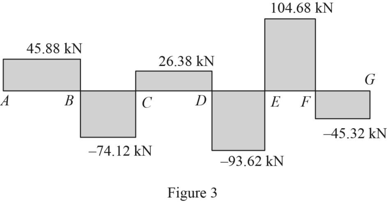
Sketch the shear diagram for the given beam as shown in Figure 3.

EBK STRUCTURAL ANALYSIS, Chapter D, Problem 10P , additional homework tip  3

Find the bending moment (M) for the given beam:

At point A,

MA=0

At point B,

MB=45.88(6)=275.3kNm

At point C,

MC=45.88(10)120(4)=21.2kNm

At point D,

MD=45.88(16)120(10)+100.5(6)=137.1kNm

At point E,

ME=45.32(8)150(4)=237.4kNm

At point F,

MF=45.32(4)=181.3kNm

At point G,

MG=0

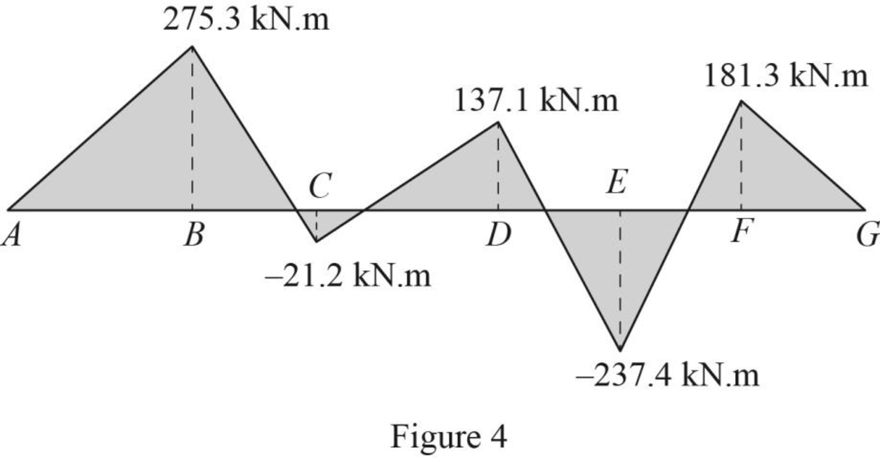
Sketch the bending moment diagram for the given beam as shown in Figure 4.

EBK STRUCTURAL ANALYSIS, Chapter D, Problem 10P , additional homework tip  4

Want to see more full solutions like this?

Subscribe now to access step-by-step solutions to millions of textbook problems written by subject matter experts!
Students have asked these similar questions
Determine the absolute maximum shear in a 60-ft-long simply supported beam due to the series of four moving concentrated loads shown in Fig. P9.14
Determine the reactions and draw the shear and bending moment diagrams for the beams shown by using the slope deflection method. PLEASE REFER TO FIG. P16.3
Draw qualitative influence lines for the vertical reactions at supports A and B, the bending moment at point B, and the shear and bending moment at point C of the beams shown in Figs. Also, show the arrangements of a uniformly distributed downward live load w to cause the maximum upward reactions at supports A and B, the maximum negative bending moment at B, the maximum negative shear at C, and the maximum positive bending moment at C.