12 in 14-in D -in R. 2 in C 1-in D. 15 in 1-in D. Figure (2-1) A stress element at A on the top surface will be subjected to a tensile bending stress and a torsional stress. This point, on the 1-in-diameter section, is the weakest section, and governs the strength of the assembly. The two stresses are
12 in 14-in D -in R. 2 in C 1-in D. 15 in 1-in D. Figure (2-1) A stress element at A on the top surface will be subjected to a tensile bending stress and a torsional stress. This point, on the 1-in-diameter section, is the weakest section, and governs the strength of the assembly. The two stresses are

Mechanics of Materials (MindTap Course List)
9th Edition
ISBN:9781337093347
Author:Barry J. Goodno, James M. Gere
Publisher:Barry J. Goodno, James M. Gere
Chapter2: Axially Loaded Members
Section: Chapter Questions
Problem 2.6.9P: A prismatic bar with a length L = 3 ft and cross-sectional area A = 8 in2 is compressed by an axial...

Related questions
Topic Video
Question
I need answer please in 10 min with my best wishes
Transcribed Image Text:2 in
12 in
4-in D.
응in R.
2 in C
1-in D.
15 in
1-in D.
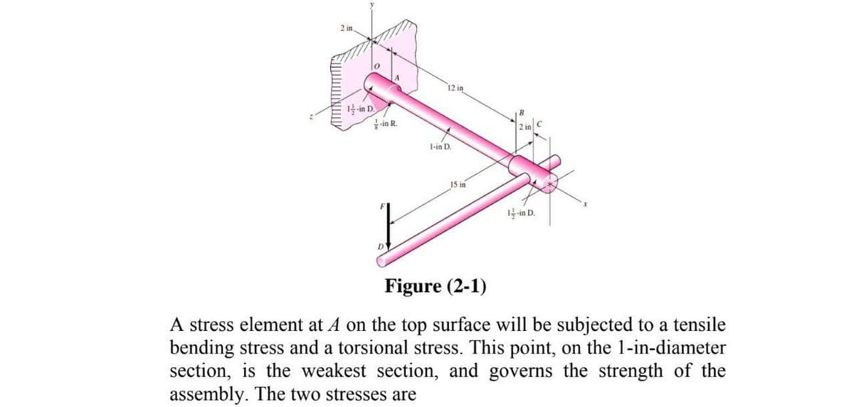
Figure (2-1)
A stress element at A on the top surface will be subjected to a tensile
bending stress and a torsional stress. This point, on the 1-in-diameter
section, is the weakest section, and governs the strength of the
assembly. The two stresses are
Expert Solution
This question has been solved!
Explore an expertly crafted, step-by-step solution for a thorough understanding of key concepts.

Step by step
Solved in 2 steps with 2 images

Knowledge Booster


Learn more about
Need a deep-dive on the concept behind this application? Look no further. Learn more about this topic, mechanical-engineering and related others by exploring similar questions and additional content below.Recommended textbooks for you
Mechanics of Materials (MindTap Course List)
Mechanical Engineering
ISBN:
9781337093347
Author:
Barry J. Goodno, James M. Gere
Publisher:
Cengage Learning
Mechanics of Materials (MindTap Course List)
Mechanical Engineering
ISBN:
9781337093347
Author:
Barry J. Goodno, James M. Gere
Publisher:
Cengage Learning