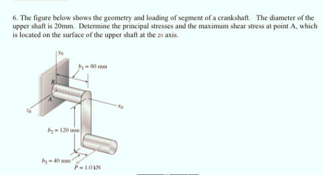
6. The figure below shows the geometry and loading of segment of a crankshaft. The diameter of the upper shaft is 20mm. Determine the principal stresses and the maximum shear stress at point A, which is located on the surface of the upper shaft at the zo axis. Omm Xo by= 120 mm 40 mm
6. The figure below shows the geometry and loading of segment of a crankshaft. The diameter of the upper shaft is 20mm. Determine the principal stresses and the maximum shear stress at point A, which is located on the surface of the upper shaft at the zo axis. Omm Xo by= 120 mm 40 mm

Mechanics of Materials (MindTap Course List)
9th Edition
ISBN:9781337093347
Author:Barry J. Goodno, James M. Gere
Publisher:Barry J. Goodno, James M. Gere
Chapter7: Analysis Of Stress And Strain
Section: Chapter Questions
Problem 7.4.24P: through 7.4-25 An clement in plane stress is subjected to stresses sx,??y,and txy. (see figure)....

Related questions

Question
Transcribed Image Text:6. The figure below shows the geometry and loading of segment of a crankshaft. The diameter of the
upper shaft is 20mm. Determine the principal stresses and the maximum shear stress at point A, which
is located on the surface of the upper shaft at the zo axis.
b-80 mm
Xo
bz = 120 mm
by- 40 mm
P-LOKN
Expert Solution
This question has been solved!
Explore an expertly crafted, step-by-step solution for a thorough understanding of key concepts.

Step by step
Solved in 3 steps with 3 images

Knowledge Booster


Learn more about
Need a deep-dive on the concept behind this application? Look no further. Learn more about this topic, mechanical-engineering and related others by exploring similar questions and additional content below.Recommended textbooks for you
Mechanics of Materials (MindTap Course List)
Mechanical Engineering
ISBN:
9781337093347
Author:
Barry J. Goodno, James M. Gere
Publisher:
Cengage Learning
Mechanics of Materials (MindTap Course List)
Mechanical Engineering
ISBN:
9781337093347
Author:
Barry J. Goodno, James M. Gere
Publisher:
Cengage Learning