
Introductory Circuit Analysis (13th Edition)
13th Edition
ISBN: 9780133923605
Author: Robert L. Boylestad
Publisher: PEARSON
expand_more
expand_more
format_list_bulleted
Related questions
Question
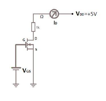
5- a-) Define the MOSFET in the figure, explain by drawing its input and output circuit characteristics.
b-) Since k=0.1 mA/V2, VGS=5V and VT=2.5V for this MOSFET, find the VDS voltage using the circuit.

Expert Solution
This question has been solved!
Explore an expertly crafted, step-by-step solution for a thorough understanding of key concepts.

Step by stepSolved in 5 steps with 11 images

Knowledge Booster


Learn more about
Need a deep-dive on the concept behind this application? Look no further. Learn more about this topic, electrical-engineering and related others by exploring similar questions and additional content below.Similar questions
- Briefly explain how the current flow is enabled in a p-Type MOSFET. Include the direction of current flow and mention the role of the source, drain, and gate.arrow_forwarda) The n-channel JFET and the D-MOSFET have very similar I-V output characteristics. Which of these two structures can be operated in enhancement mode and why is that possible?arrow_forwardThis question would help revise concepts related to MOS device and basic circuit design. Please mark all correct answers to the following multiple choice questions. 1.1. Which of the following are true about MOSFET devices? (a) MOS stands for "Metallurgy Of Semiconductors" (b) MOSFET current conduction is due to drift phenomenon (c) An externally induced voltage at the gate is fundamental to inversion layer (d) Naming of "Source" and "Drain" regions are only dependent on aspect ratio 1.2. Which of the following are true about NMOS transistors (a) The threshold voltage can be positive or negative depending on geometry (b) Channel length modulation parameter (A) is always positive (c) Current flows from drain to source (d) Threshold voltage is a fixed value based on process, it cannot be changed by external voltages 1.3. In a MOS device (a) Cas and CGp both have both geometry and voltage dependencies (b) Cas is takes minimum value at saturation while CGD goes to maximum value (c) CoB and…arrow_forward
- Pls help ASAP. Pls show all work.arrow_forwardIDSS=8mA , VP =-4VTo help plot the DC load line VGS=VG-IDRSa)Attach a Plot of JFET Characteristic Curve as shown in Figureb)What is the approximate VGSQ?c)What is the approximate IDQ in mA?d)Determine source voltage VS.e)Calculate the drain voltage VD.f)Calculate the drain-to-source voltage VDS.arrow_forwardwith the aid of a diagram describe a simple common emitter circuit with npn bipolar transitor and discus the relationship between base emitter voltage and base currentarrow_forward
- 7. MOSFET circuit The MOSFET in the circuit below has V, = 1 V and kn = 4 mA/V². a) Is the MOSFET operating in saturation or in the triode region? b) Determine the drain current Ip and Vout: + 5 V 5 k Voutarrow_forward(a) What is the output current IO in the circuitshown if −VEE = −10 V andR = 20 ohm? Assume that the MOSFET is saturated.(b) What is the minimum voltage VDDneeded to saturate the MOSFET if VTN = 2.5 Vand K'n = 0.25 A/V2. (c) What must be the powerdissipation ratings of resistor R and the FET.arrow_forward(b) Draw the ID - VD curves for this MOSFET for ±VD for V₁ = 0 and V₁ = 1 V. VȚ = 1V. n V₁ + p-type D ID V₁arrow_forward
- In a full-bridge dc-dc converter using PWM bipolar voltage switching, analytically obtain the value of (V/V) which results in the maximum (peak-peak) ripple in the output current i,. Calculate this ripple in terms of Va, La, and farrow_forwardDetermine in which mode (depletion, enhancement or neither) each D-MOSFET in the figure below.arrow_forwardDetermine vo versus v₁ for the circuit shown in Figure 2. Assume that the MOSFET operates in saturation and is characterized by the parameters K and VT. Vs R₁ www Figure 2 wwww RL R₂ wwwww VO Note: assuming the MOSFET works at normal saturation regime and ips= (VDS -VT)²2 K 2arrow_forward
arrow_back_ios
SEE MORE QUESTIONS
arrow_forward_ios
Recommended textbooks for you
- Introductory Circuit Analysis (13th Edition)Electrical EngineeringISBN:9780133923605Author:Robert L. BoylestadPublisher:PEARSON
 Delmar's Standard Textbook Of ElectricityElectrical EngineeringISBN:9781337900348Author:Stephen L. HermanPublisher:Cengage Learning
 Programmable Logic ControllersElectrical EngineeringISBN:9780073373843Author:Frank D. PetruzellaPublisher:McGraw-Hill Education
  Fundamentals of Electric CircuitsElectrical EngineeringISBN:9780078028229Author:Charles K Alexander, Matthew SadikuPublisher:McGraw-Hill Education
 Electric Circuits. (11th Edition)Electrical EngineeringISBN:9780134746968Author:James W. Nilsson, Susan RiedelPublisher:PEARSON
 Engineering ElectromagneticsElectrical EngineeringISBN:9780078028151Author:Hayt, William H. (william Hart), Jr, BUCK, John A.Publisher:Mcgraw-hill Education,
Introductory Circuit Analysis (13th Edition)
Electrical Engineering
ISBN:9780133923605
Author:Robert L. Boylestad
Publisher:PEARSON
Delmar's Standard Textbook Of Electricity
Electrical Engineering
ISBN:9781337900348
Author:Stephen L. Herman
Publisher:Cengage Learning
Programmable Logic Controllers
Electrical Engineering
ISBN:9780073373843
Author:Frank D. Petruzella
Publisher:McGraw-Hill Education
Fundamentals of Electric Circuits
Electrical Engineering
ISBN:9780078028229
Author:Charles K Alexander, Matthew Sadiku
Publisher:McGraw-Hill Education
Electric Circuits. (11th Edition)
Electrical Engineering
ISBN:9780134746968
Author:James W. Nilsson, Susan Riedel
Publisher:PEARSON
Engineering Electromagnetics
Electrical Engineering
ISBN:9780078028151
Author:Hayt, William H. (william Hart), Jr, BUCK, John A.
Publisher:Mcgraw-hill Education,