Question 6 For the loaded beam shown in Figure Q6 below, consider section M-M and determine the following: 61 The maximum shear stress in that section 62 The shearing stress at point P pwipe up for tirer 03m 04m 100 mm


Q: Q 1: A simply supported beam as shown in figure (1-A) below, having an I-cross section, has an over…
A:
Q: A beam ABCDE is 5 m in length and loaded as shown in Figure Q3. Draw the S.F. and B.M. diagrams for…
A: The maximum bending stress occurs at the maximum bending moment and is given by,…
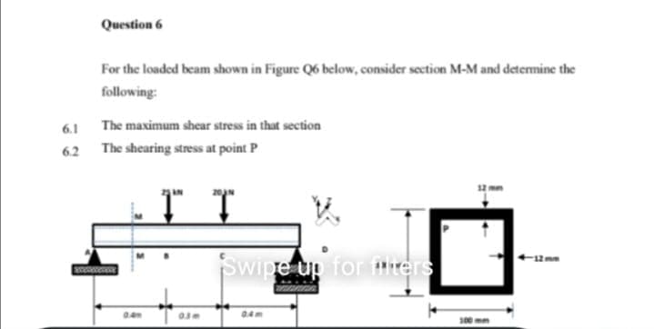
Q: For the loaded beam shown in Figure Q6 below, consider section M-M and detemine the following: 6.1…
A: Given Data: Length of the beam, L=0.4+0.3+0.4=1.1 m
Q: Q : A simply supported beam shown in Figure (3-A) below, has the cross section shown in figure (3-B)…
A:
Q: Q3(a) A wood beam with a rectangular section is found to have the insufficient load capacity. So an…
A: according to the given details
Q: В C 3 m 3 m
A:
Q: |1200 Ib | 1200 Ib 3 ft R2
A: Note: As per bartelby guideline first three subpart are solved. please upload other part separately…
Q: Problem 3: Computation of Shear stresses A 6m long beam with a 50 mm x 50 mm cross section is…
A:
Q: The cross-sectional dimensions of the beam shown in Figure are ro = 115 mm and ri = 95 mm. Given Mz…
A: Moment of inertia is given asI=π64D4-d4I=π642×1154-2×954I=73.39×106 mm4perpenficular distance…
Q: 25 kips 20 in.- Figure 1 10 in. 25 kips 20 in. B 7.25 in. Sin.- b 1.5 in. 1.5 in.
A:
Q: A beam with rigid support at A, pin connection at C and roller at D has the geometry and loads as…
A:
Q: Example 4 The simply supported beam in Figure below has a rectangular 3kN cross section 100 mm wide…
A: Given: Uniform distributed load at the beam is, w=1.5 kN/m . Point load acting at point B is 3 kN .…
Q: 4 ft Calculate the average shear stress in MPa of the pins B and C on the frame shown in the figure.…
A:
Q: Example 4 The simply supported beam in Figure below has a rectangular 3kN cross section 100 mm wide…
A: Solution: To find support reactions at A and B, considering static equilibrium,…
Q: The composite beam in the figure is made of steel and aluminum. Beam In steel and aluminum as it is…
A: Given: Esteel=210GPa Eal=70GPa M=2kNm Solution: The position of the neutral axix is exactly at the…
Q: Q.2) For a T section beam with twolong wooden planks whose dimensions (all in mm) are shown in…
A:
Q: The overhanging beam shown in Figure 2 is subjected to two point loads, P at the free end D and 2P…
A: NOTE:- As per our company guidelines we are supposed to answer only first 3 sub-parts. Kindly repost…
Q: Situation 12: The simply supported beam in FIGURE SOM-008 is fabricated by gluing together three 160…
A: For the given simply supported beam maximum bending stress in the planks = 24 MPa To determine…
Q: (a) The tubular rotor shaft of a wind turbine shown in Figure 3(a) is of 50 mm and 40 mm outer and…
A: Given data Outer Diameter of Tubular shaft = Do = 50 mm = 0.05 mInner Diameter of Tubular Shaft = Di…
Q: The simply supported beam AB as shown in Figure Q3(a) has a uniform load of intensity, w - 15 kN/m…
A: Given we have w=15 KN/mINA=3.6 X 106 mm4RA=RB (symmetric loading)⇒RA+RB=15(0.6+1.8)⇒ZRA=1.5 X…
Q: Q1: A simply supported beam as shown in figure (1-A) below, having an I-cross section, has an over…
A: Given figure
Q: Calculate the average shear stress in MPa of the pins B and C on the frame shown in the figure. Note…
A:
Q: For the shaft section depicted in Figure Ql.13, a shear force acts in the y direction, V., and a…
A:
Q: 6.8-3 An IPN 240 steel beam has the cross section shown in the figure. The dimensions are b = 106…
A: Symmetric section τmax is at neutral axis-
Q: . Determine the shear stresses along sections A-A, B-B, C-C and D-D. b. Plot the shear stress…
A:
Q: Figure Q1 shows one ‘L’ shaped beam ACD which is built-in at one end. It is loaded with load F=3 kN…
A:
Q: 6. A cantilever beam with cross section shown in Figure 4 and span of 3.6 concentrated load (P) at…
A: Givenmaximum shear stress on section τmax=4MPa
Q: if the cross-section shown in the figure has shear stress of 300psi at point P( located 0.25 in…
A:
Q: a) b) c) A loaded cantilever beam is shown in Figure 3. Determine the horizontal and vertical…
A:
Q: Q2) A rectangular beam 120mm wide by 400mm deep is loaded as shown in the figure. Find "P" to cause…
A: Any action that can change the state of motion is force. Force is described by its magnitude, point…
Q: For the loaded beam shown in Figure Q6 below, consider section M-M and determine the following: 6.1…
A:
Q: For the loaded beam shown in Figure Q6 below, consider section M-M and determine the following: 6.1…
A: Solution - First we will find out the reaction force developed at points A and D Then using the…
Q: moment of inertia Iz 465.8 in“, determine: Problem 3: The internal shear force V at a certain ection…
A: we have to calculate shear stress
Q: A steel beam ABC carries a uniformly distributed load of w (kN/m) over the unsupported length BC, as…
A:
Q: Rectangular cross-section and width given the loading state in the figure Bending safety stress of…
A:
Q: (B) // The straight beam with distribution load as shown in figure B is simply supported by a pin at…
A:
Q: Q5: A 8 m long simply supported steel beam with a hollow rectangular cross-section carries a 20 kN…
A:
Q: A Simply Supported beam of 4 m span is in the form of hollow square bar (120x120 mm) as shown in…
A:
Q: simply supported beam in Figure below has a rectangular s section 120 mm wide and 200 mm high: 1.…
A:
Q: 5.8-6) A cantilever beam of length L = 2 m sup- ports a load P = 8.0 kN (see figure). The beam is…
A:
Q: Rectangular section and width given in the figure The bending safety stress of the beam with b = 150…
A:
Q: HOMEWORK: Q1/ A beam carries the loads shown in figure, if the tensile stress must not exceed 20 MPa…
A: Find load P
Q: A uniformly distributed load of 200 lb/ft is carried on a simply supported span. If the cross…
A:
Q: A steel beam ABC carries a concentrated load of P (kN) at B and C, as shown in Figure Q3(a). The…
A: Drawing the free body diagram as shown below, ∑Fy=0VA+VB=2P∑MA=0 P×10+P×15=VB×10VB=2.5P, VA=-0.5P…
Q: The Cantilever beam in Fig. 5, has a circular cross section (diameter 100 mm) (a)find the shear…
A: Given data, d = Diameter of the circular cross-section = 100 mm w = Intensity of the uniform load =…
Q: How high should the height h of the beam cross-section be at least so that the stresses that will…
A: find reaction ant A and B. then draw S.F.D. and B.M.D. and find out maximum bending moment and…
Q: b) The simply supported beam as shown in Figure 2 is made of five planks glued together at A and B.…
A:
Q: Q.3. The wooden box beam shown in figure (3a) is fabricated from four boards fastened together with…
A:
Q: The cross-sectional dimensions of the beam shown in Figure are ro = 115 mm and ri = 95 mm. Given Mz…
A:

Step by step
Solved in 2 steps with 2 images


- A square tube section has side dimension of 20 in. arid thickness of 0.5 in. If the section is used for a 10-ft-long beam subjected to 1250 kip-in, torque at both ends, calculate the maximum shear stress and the angle of twist between the ends. Use G = 11,600 ksi.A cantilever beam of length L = 2 m supports a load P = 8,0 kN (sec figure). The beam is made of wood with cross-sectional dimensions 120 mm x 200 mm. Calculate the shear stresses due to the load/"at points located 25 mm, 50 mm, 75 mm, and 100 mm from the top surface of the beam. From these results, plot a graph showing the distribution of shear stresses from top to bottom of the beam.A thin-walled steel tube of rectangular cross section (see figure) has centerline dimensions b = 150 mm and h = 100 mm. The wall thickness t is constant and equal to 6.0 mm. Determine the shear stress in the tube due to a torque T = 1650 N · m. Determine the angle of twist (in degrees) if the length L of the tube is 1.2 m and the shear modulus G is 75 GPa.
- A steel beam of length L = 16 in. and cross-sectional dimensions h = 0.6 in. and h = 2 in. (see figure) supports a uniform load of intensity if = 240 lb/in., which includes the weight of the beam. Calculate the shear stresses in the beam (at the cross section of maximum shear force) at points located 1/4 in., 1/2 in., 3/4 in., and I in, from the top surface of the beam. From these calculations, plot a graph showing the distribution of shear stresses from top to bottom of the beam.A wood beam AB on simple supports with span length equal to 10 ft is subjected to a uniform load of intensity 125 lb/ft acting along the entire length of the beam, a concentrated load of magnitude 7500 lb acting at a point 3 ft from the right-hand support, and a moment at A of 18,500 ft-lb (sec figure). The allowable stresses in bending and shear, respectively, are 2250 psi and 160 psi. From the table in Appendix G, select the lightest beam that will support the loads (disregard the weight of the beam). Taking into account the weight of the beam (weight density = 35 lb/ft3), verify that the selected beam is satisfactory, or if it is not, select a new beam.A wood beam reinforced by an aluminum channel section is shown in the figure. The beam has a cross section of dimensions 150 mm x 250 mm, and the channel has a uniform thickness of 6.5 mm. If the allowable stresses in the wood and aluminum are 8 M Pa and 38 M Pa, respectively, and if their moduli of elasticity are in the ratio 1 to 6, what is the maximum allowable bending moment for the beam?
- A vertical pole of solid, circular cross section is twisted by horizontal forces P = 5kN acting at the ends of a rigid horizontal arm AB (see figure part a). The distance from the outside of the pole to the line of action of each force is c = 125 mm (sec figure part b) and the pole height L = 350 mm. (a) If the allowable shear stress in the pole is 30 MPa, what is the minimum required diameter dminof the pole? (b) What is the torsional stiffness of the pole (kN · m/rad)? Assume that G = 28 GPa. (c) If two translation al springs, each with stiffness k =2550 kN/m, are added at 2c/5 from A and B (see figure part c), repeat part (a) to find dmin. Hint: Consider the pole and pair of springs as "springs in parallel."A thin-walled steel tube having an elliptical cross section with constant thickness t (see figure) is subjected to a torque T = 18 kip-in. Determine the shear stress and the rate of twist in degrees per inch) if G = 12 × 106 psi, t = 0.2 in., a = 3 in., and b = 2 in. Note: See Appendix E, Case 16, for the properties of an ellipse.A wood pole with a solid circular cross section (d = diameter) is subjected to a triangular distributed horizontal force of peak intensity q0= 20 lb/in. (see figure). The length of the pole is L = 6 ft, and the allowable stresses in the wood arc 1900 psi in bending and 120 psi in shear. Determine the minimum required diameter of the pole based upon (a) the allowable bending stress, and (b) the allowable shear stress.
- A full quarter-circular fillet is used at the shoulder of a stepped shaft having diameter D2= 1.0 in. (see figure), A torque T = 500 lb-in. acts on the shaft. Determine the shear stress at the stress concentration for values as follows: D1= 0.7,0.8, and 0.9 in. Plot a graph showing versus D?A circular steel tube of length L = 1.0 m is loaded in torsion by torques T (see figure). (a) If the inner radius of the tube is r1= 45 mm and the measured angle of twist between the ends is 0.5°, what is the shear strain y1(in radians) at the inner surface? (b) If the maximum allowable shear strain is 0.0004 rad and the angle of twist is to be kept at 0.45° by adjusting the torque T, what is the maxi mum permissible outer radius (r2)max?A beam of wide-flange shape, W 8 x 28, has the cross section shown in the figure. The dimensions are b = 6.54 in., h = 8.06 in., fw = 0.285 in., and tf = 0.465 in.. The loads on the beam produce a shear force V = 7.5 kips at the cross section under consideration. Use center line dimensions to calculate the maximum shear stress raiaxin the web of the beam. Use the more exact analysis of Section 5,10 in Chapter 5 to calculate the maximum shear stress in the web of the beam and compare it with the stress obtained in part .