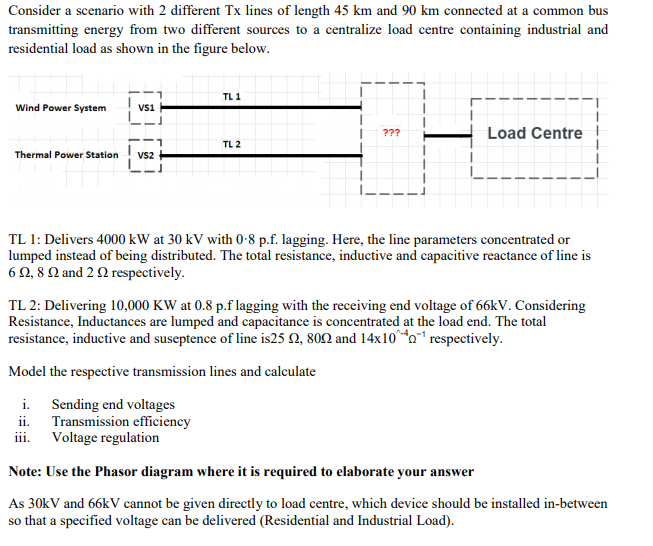
Consider a scenario with 2 different Tx lines of length 45 km and 90 km connected at a common bus transmitting energy from two different sources to a centralize load centre containing industrial and residential load as shown in the figure below. TL 1 Wind Power System Vsi 7?? Load Centre TL 2 Thermal Power Station Vs2 TL 1: Delivers 4000 kW at 30 kV with 0-8 p.f. lagging. Here, the line parameters concentrated or lumped instead of being distributed. The total resistance, inductive and capacitive reactance of line is 6Ω.8Ω and 2 Ω respectively. TL 2: Delivering 10,000 KW at 0.8 p.f lagging with the receiving end voltage of 66kV. Considering Resistance, Inductances are lumped and capacitance is concentrated at the load end. The total resistance, inductive and suseptence of line is25 N, 802 and 14x10^*o*' respectively. Model the respective transmission lines and calculate i. Sending end voltages ii. Transmission efficiency iii. Voltage regulation Note: Use the Phasor diagram where it is required to elaborate your answer As 30kV and 66kV cannot be given directly to load centre, which device should be installed in-between so that a specified voltage can be delivered (Residential and Industrial Load).


Load flow analysis
Load flow analysis is a study or numerical calculation of the power flow of power in steady-state conditions in any electrical system. It is used to determine the flow of power (real and reactive), voltage, or current in a system under any load conditions.
Nodal Matrix
The nodal matrix or simply known as admittance matrix, generally in engineering term it is called Y Matrix or Y bus, since it involve matrices so it is also referred as a n into n order matrix that represents a power system with n number of buses. It shows the buses' nodal admittance in a power system. The Y matrix is rather sparse in actual systems with thousands of buses. In the power system the transmission cables connect each bus to only a few other buses. Also the important data that one needs for have a power flow study is the Y Matrix.
Types of Buses
A bus is a type of system of communication that transfers data between the components inside a computer or between two or more computers. With multiple hardware connections, the earlier buses were parallel electrical wires but the term "bus" is now used for any type of physical arrangement which provides the same type of logical functions similar to the parallel electrical bus. Both parallel and bit connections are used by modern buses. They can be wired either electrical parallel or daisy chain topology or are connected by hubs which are switched same as in the case of Universal Serial Bus or USB.

Step by step
Solved in 6 steps with 1 images


