
Introductory Circuit Analysis (13th Edition)
13th Edition
ISBN: 9780133923605
Author: Robert L. Boylestad
Publisher: PEARSON
expand_more
expand_more
format_list_bulleted
Related questions
Concept explainers
Question
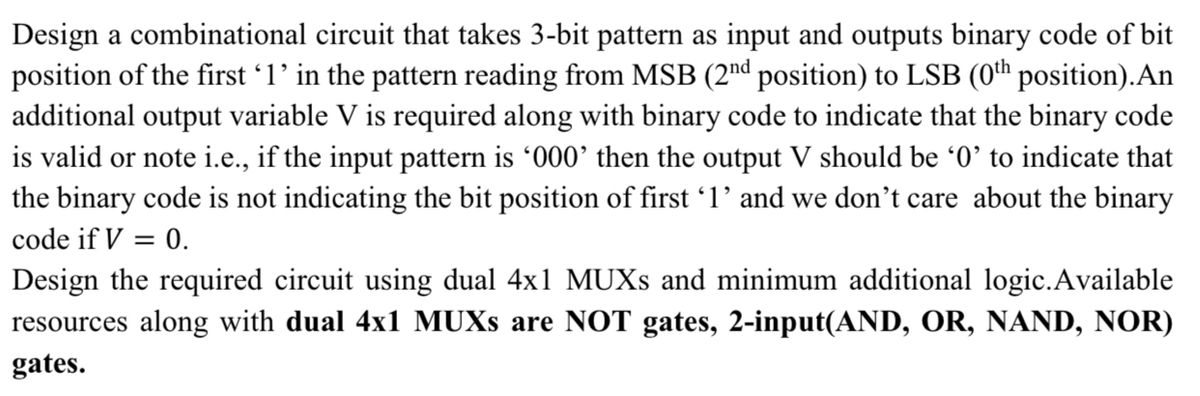

Transcribed Image Text:Design a combinational circuit that takes 3-bit pattern as input and outputs binary code of bit
position of the first 1' in the pattern reading from MSB (2nd position) to LSB (0th position).An
additional output variable V is required along with binary code to indicate that the binary code
is valid or note i.e., if the input pattern is '000' then the output V should be '0' to indicate that
the binary code is not indicating the bit position of first 1' and we don't care about the binary
code if V = 0.
Design the required circuit using dual 4x1 MUXS and minimum additional logic.Available
resources along with dual 4x1 MUXS are NOT gates, 2-input(AND, OR, NAND, NOR)
gates.
Expert Solution
This question has been solved!
Explore an expertly crafted, step-by-step solution for a thorough understanding of key concepts.

Step by stepSolved in 4 steps with 6 images

Knowledge Booster


Learn more about
Need a deep-dive on the concept behind this application? Look no further. Learn more about this topic, electrical-engineering and related others by exploring similar questions and additional content below.Similar questions
- I need the answer as soon as possiblearrow_forwardYour task is to implement a Full Adder Using TWO 4:1 Multiplexers but this time connect Cin and Y to the Select Inputs of the Multiplexers,and connect 1’s, 0’s, X, or X’ to each Data Input.arrow_forwardWhich of the following is true about quantization? a. Actual quantization error is the same all throughout the process.b. The signal to noise ratio is the same all throughout the quantization process.c. The smaller the resolution the less quantization error is introducedd. All of the choicesarrow_forward
- | Solve all parts. Will give thumb's up| If you can't do all please don't attempt the questions.arrow_forwardGiven a 5-bit ADC with the following reference values Vref= -2V and 12V, what is the voltage represented by the output sequence 01010?arrow_forward1What will be the state of a MOD64 counter after 90 input pulses if the starting state=000000?A.100100B.011010C.010110D.011100 2.A MOD 32 counter is holding the count 101112. What will the count be after 31 clock pulses?A.10100B.10010C.10000D.10110arrow_forward
- Q2 - Pseudo-Random Number Generator a) The following circuit is a pseudo-random number generator which uses linear feedback shift registers to produce a stream of outputs. The XOR tap at index '1' is responsible for generating this sequence of outputs. Fill in the table for the outputs of the 4 registers after each clock cycle. The initial output state is already provided in the first row. You can stop when the output starts to repeat and just say that it is repeating. QO Q1 Q2 Q3 ID ClockEdge # Q3 Q2 Q1 QO 1 1 2 3 7 10 11 12 13 14 00arrow_forwardA sequence detector is designed to detect precisely 3 digital inputs, with overlapping sequences detectable. For the sequence (1,0,1) and input data (1,1,0,1,0,0,1,1,0,1,0,1,1,0), what is the output of this detector?arrow_forwardI need an expert solution to the question correctly.arrow_forward
- 3. The timing diagram below is for the 8-bit register block shown. Complete the timing diagram by filling in the output (q) signal. load q(N-1.0)+ cik cir Input(N-1.0) cik Register cir load input 45 A3 4B FF 44 01 02 CA 66 7A 98 9arrow_forwardDesign a combinational circuit with the four inputs A,B.C, and D, and three outputs X, Y, and Z. When the binary input is odd number, the binary output is one lesser than the input. When the binary input is even number the binary output is one greate than the input. Implement the function using multiplexers with minimal input and select line.arrow_forwardDevelop the Q output waveforms for a 74HC190 up/down counter with the input waveforms shown in figure below. A binary 0 is on the data inputs. Start with a count of 0000. CLK CTEN LOADarrow_forward
arrow_back_ios
SEE MORE QUESTIONS
arrow_forward_ios
Recommended textbooks for you
- Introductory Circuit Analysis (13th Edition)Electrical EngineeringISBN:9780133923605Author:Robert L. BoylestadPublisher:PEARSON
 Delmar's Standard Textbook Of ElectricityElectrical EngineeringISBN:9781337900348Author:Stephen L. HermanPublisher:Cengage Learning
 Programmable Logic ControllersElectrical EngineeringISBN:9780073373843Author:Frank D. PetruzellaPublisher:McGraw-Hill Education
  Fundamentals of Electric CircuitsElectrical EngineeringISBN:9780078028229Author:Charles K Alexander, Matthew SadikuPublisher:McGraw-Hill Education
 Electric Circuits. (11th Edition)Electrical EngineeringISBN:9780134746968Author:James W. Nilsson, Susan RiedelPublisher:PEARSON
 Engineering ElectromagneticsElectrical EngineeringISBN:9780078028151Author:Hayt, William H. (william Hart), Jr, BUCK, John A.Publisher:Mcgraw-hill Education,
Introductory Circuit Analysis (13th Edition)
Electrical Engineering
ISBN:9780133923605
Author:Robert L. Boylestad
Publisher:PEARSON
Delmar's Standard Textbook Of Electricity
Electrical Engineering
ISBN:9781337900348
Author:Stephen L. Herman
Publisher:Cengage Learning
Programmable Logic Controllers
Electrical Engineering
ISBN:9780073373843
Author:Frank D. Petruzella
Publisher:McGraw-Hill Education
Fundamentals of Electric Circuits
Electrical Engineering
ISBN:9780078028229
Author:Charles K Alexander, Matthew Sadiku
Publisher:McGraw-Hill Education
Electric Circuits. (11th Edition)
Electrical Engineering
ISBN:9780134746968
Author:James W. Nilsson, Susan Riedel
Publisher:PEARSON
Engineering Electromagnetics
Electrical Engineering
ISBN:9780078028151
Author:Hayt, William H. (william Hart), Jr, BUCK, John A.
Publisher:Mcgraw-hill Education,