
Understanding Motor Controls
4th Edition
ISBN: 9781337798686
Author: Stephen L. Herman
Publisher: Delmar Cengage Learning
expand_more
expand_more
format_list_bulleted
Related questions
Question
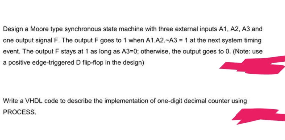

Transcribed Image Text:Design a Moore type synchronous state machine with three external inputs A1, A2, A3 and
one output signal F. The output F goes to 1 when A1.A2.-A3 = 1 at the next system timing
event. The output F stays at 1 as long as A3=0; otherwise, the output goes to 0. (Note: use
a positive edge-triggered D flip-flop in the design)
Write a VHDL code to describe the implementation of one-digit decimal counter using
PROCESS.
Expert Solution
This question has been solved!
Explore an expertly crafted, step-by-step solution for a thorough understanding of key concepts.

Step by stepSolved in 2 steps with 5 images

Knowledge Booster

Similar questions
- Q: Discuss the control system (the level controller and the temperature controllers) shown in figure (2). Specify the controlled and manipulated variable in each case. Discuss the type of the controller used in each case, that is, a simple feedback controller, a feedforward controller, a cascade controller, etc. Draw the block diagram of the temperature control loops. Feed Reactor temperature set point (master) TC Water surge tank i Jacket itemperature i set point (slave) TC LC-LT Reactor Cooling water out Product Cooling water makeup Circulation pump Figure (2)arrow_forwardPlot the unit step and unit ramp response curve for the following closed loop transferfunction using MATLAB. Indicate clearly the input and output in your plot Auto Controls provide matlab codearrow_forwardBelow is an open loop transfer function which is given: A(s) A(s) = = 0.1(s +14) (s+7)(s + 5) Use matlab's bode function and plot its bode diagram. Show the figure Use the following MATLAB script and write a code for bode plotting concerning the open loop transfer function. Clear Close all clc w 0. 1:0.001:100; ns = length (w); for i=1:nS %Write the code here endarrow_forward
- Traffic Light System Construct a PLC program for a traffic light system with the following condition: The green light will be ON for 10 second, followed by the yellow light for 3 second and red light for 20. The system will run continuously until the START/STOP switch is deactivated. Figure 12: The traffic light system Two Directional Control of Traffic Light Extend the PLC program for the traffic light system with the following condition:. Red = north/south Green = north/south Amber = north/south Green = east/west Amber = east/west Red = east/west -25 s ·5 s 25 s 5 sarrow_forwardDon't copy from other platform Thank youarrow_forwarddont do the simscape piecearrow_forward
- Auto Controls Design a PID controller for thefollowing system so that the modified system satisfies the followingspecifications : 1. settling time ,ts = 1.96 s and % Overshoot Mp = 70.7 % Assume a non-dominant pole at s = -15 to solve the problem The plot the compensated andThen plot the uncompensated system in MATLAB. what can you see from the plot ? what is your observation ?arrow_forwardQ1. A mechanical system is shown in the following figure, where external force u₁ is the input and displacement y₂ is the output. The force acting on m₂ has a linear relationship with u₁ as u₂-Au₁. • List system equations and do Laplace transform to the system equations; • Draw block diagram of the control system. (Please construct the block diagram from system equations directly, do not derive or combine the equations. Do not need to reduce it) YI Y b₁ m₁ 11 112 + m₂ wwwarrow_forwardPlease show all work for FBD and equatiosnarrow_forward
- do not solve the last part ofthe question which states “Obtain the steady-state error when the disturbance qd is a unit-stepfunction”.arrow_forwardFigures 4: show a pneumatic controller. The pneumatic relay has the characteristic that pc=K pb , where K>0. What kind of control action does this controller produce? a. Derive the mathematical model for the system b. Derive the transfer function Pc(s)/E(s) -Solve step by step Orifice F+Ph R₁ Actuating error signal Flapper Nozzle. x+x F+Pe thinkarrow_forwardCan someone help me please and solve this question with steps and draw the block digram and find the transfer function of the system Thanksarrow_forward
arrow_back_ios
SEE MORE QUESTIONS
arrow_forward_ios
Recommended textbooks for you
- Understanding Motor ControlsMechanical EngineeringISBN:9781337798686Author:Stephen L. HermanPublisher:Delmar Cengage Learning
Understanding Motor Controls
Mechanical Engineering
ISBN:9781337798686
Author:Stephen L. Herman
Publisher:Delmar Cengage Learning