a) Draw impedance diagram in per unit, by using 100-MVA base. Select 20kV as the base voltage for generator section. Use parameter of equipment for the single diagram shown in Figure 1, and specification as per Table 1. Assume the length of transmission line is in the range of value in the table. T1 T2 Vm 1 Line 2 G M Figure 1: Single line Diagram Table 1: Equipment Rating Specification No Equipment Specification 1 Motor Load 18 kV, 50 MW, power factor = 0.8 - 0.9 2 Transformer 2 200/20 kV, 50 MVA, X = 10% Transmission Line 200 kV, Length = 4km - 15km, Z = 0.06 + j0.06 Q/m 4 Transformer 1 20/200 kV, 100 MVA, X = 5% Generator 1 20 kV, 70 MVA, X = 9% b) The motor is drawing 45 MVA with lagging power factor in the range of 0.8~0.9 at a line-to-line terminal voltage of 18 kV. Determine the terminal voltage and the internal emf of the generator in per unit and in kV.
a) Draw impedance diagram in per unit, by using 100-MVA base. Select 20kV as the base voltage for generator section. Use parameter of equipment for the single diagram shown in Figure 1, and specification as per Table 1. Assume the length of transmission line is in the range of value in the table. T1 T2 Vm 1 Line 2 G M Figure 1: Single line Diagram Table 1: Equipment Rating Specification No Equipment Specification 1 Motor Load 18 kV, 50 MW, power factor = 0.8 - 0.9 2 Transformer 2 200/20 kV, 50 MVA, X = 10% Transmission Line 200 kV, Length = 4km - 15km, Z = 0.06 + j0.06 Q/m 4 Transformer 1 20/200 kV, 100 MVA, X = 5% Generator 1 20 kV, 70 MVA, X = 9% b) The motor is drawing 45 MVA with lagging power factor in the range of 0.8~0.9 at a line-to-line terminal voltage of 18 kV. Determine the terminal voltage and the internal emf of the generator in per unit and in kV.

Power System Analysis and Design (MindTap Course List)
6th Edition
ISBN:9781305632134
Author:J. Duncan Glover, Thomas Overbye, Mulukutla S. Sarma
Publisher:J. Duncan Glover, Thomas Overbye, Mulukutla S. Sarma
Chapter9: Unsymmetrical Faults
Section: Chapter Questions
Problem 9.33P

Related questions

Question
100%
All questions please. Thank you
Transcribed Image Text:Question 1
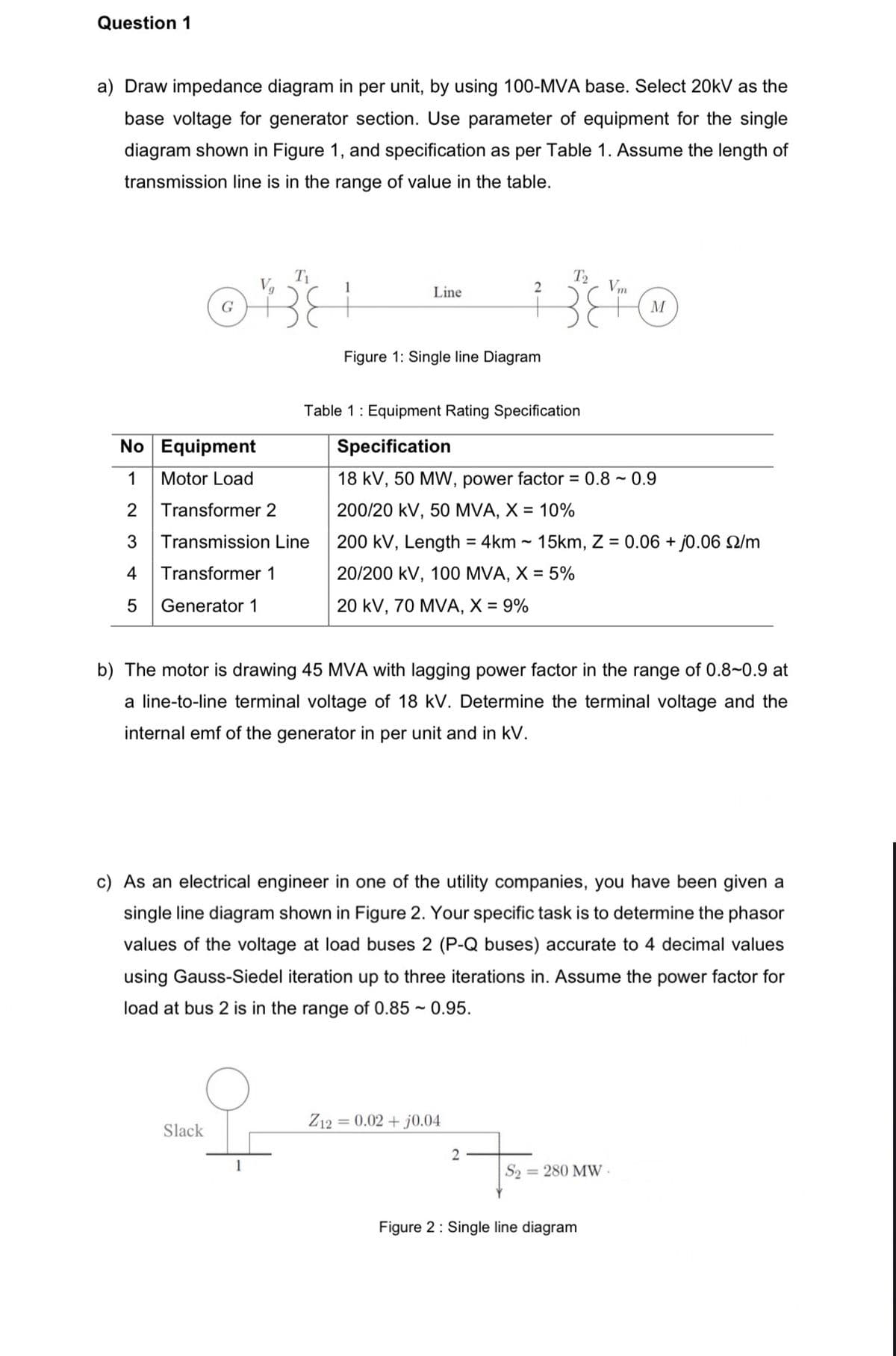
a) Draw impedance diagram in per unit, by using 100-MVA base. Select 20kV as the
base voltage for generator section. Use parameter of equipment for the single
diagram shown in Figure 1, and specification as per Table 1. Assume the length of
transmission line is in the range of value in the table.
T1
T2
Vm
Line
G
M
Figure 1: Single line Diagram
Table 1: Equipment Rating Specification
No Equipment
Specification
1
Motor Load
18 kV, 50 MW, power factor = 0.8 ~ 0.9
2
Transformer 2
200/20 kV, 50 MVA, X = 10%
Transmission Line
200 kV, Length = 4km - 15km, Z = 0.06 + j0.06 Q/m
4
Transformer 1
20/200 kV, 100 MVA, X = 5%
5
Generator 1
20 kV, 70 MVA, X = 9%
b) The motor is drawing 45 MVA with lagging power factor in the range of 0.8~0.9 at
a line-to-line terminal voltage of 18 kV. Determine the terminal voltage and the
internal emf of the generator in per unit and in kV.
c) As an electrical engineer in one of the utility companies, you have been given a
single line diagram shown in Figure 2. Your specific task is to determine the phasor
values of the voltage at load buses 2 (P-Q buses) accurate to 4 decimal values
using Gauss-Siedel iteration up to three iterations in. Assume the power factor for
load at bus 2 is in the range of 0.85 ~ 0.95.
Z12 = 0.02 + j0.04
Slack
1
S2 = 280 MW
Figure 2: Single line diagram
Expert Solution
This question has been solved!
Explore an expertly crafted, step-by-step solution for a thorough understanding of key concepts.

This is a popular solution!

Trending now
This is a popular solution!

Step by step
Solved in 4 steps with 1 images

Knowledge Booster


Learn more about
Need a deep-dive on the concept behind this application? Look no further. Learn more about this topic, electrical-engineering and related others by exploring similar questions and additional content below.Recommended textbooks for you
Power System Analysis and Design (MindTap Course …
Electrical Engineering
ISBN:
9781305632134
Author:
J. Duncan Glover, Thomas Overbye, Mulukutla S. Sarma
Publisher:
Cengage Learning
Power System Analysis and Design (MindTap Course …
Electrical Engineering
ISBN:
9781305632134
Author:
J. Duncan Glover, Thomas Overbye, Mulukutla S. Sarma
Publisher:
Cengage Learning