Four impedance loads are connected in parallel across a source as shown below. Load 1 absorbs 3 kW and delivers 6 kvars, Load 2 absorbs 6 kW and delivers 3 kvars, Load 3 absorbs 6 kVA at 0.8 leading and Load 4 absorbs 3 kVA at 0.6 lagging. Show that the current supplied to each load is equal to the total current generated. 240 V(rms) Z3 || Z.| Z2
Four impedance loads are connected in parallel across a source as shown below. Load 1 absorbs 3 kW and delivers 6 kvars, Load 2 absorbs 6 kW and delivers 3 kvars, Load 3 absorbs 6 kVA at 0.8 leading and Load 4 absorbs 3 kVA at 0.6 lagging. Show that the current supplied to each load is equal to the total current generated. 240 V(rms) Z3 || Z.| Z2

Power System Analysis and Design (MindTap Course List)
6th Edition
ISBN:9781305632134
Author:J. Duncan Glover, Thomas Overbye, Mulukutla S. Sarma
Publisher:J. Duncan Glover, Thomas Overbye, Mulukutla S. Sarma
Chapter2: Fundamentals
Section: Chapter Questions
Problem 2.30MCQ: Under balanced operating conditions, consider the three-phase complex power delivered by the...

Related questions
Question
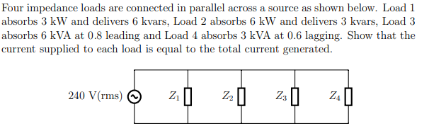
Transcribed Image Text:Four impedance loads are connected in parallel across a source as shown below. Load 1
absorbs 3 kW and delivers 6 kvars, Load 2 absorbs 6 kW and delivers 3 kvars, Load 3
absorbs 6 kVA at 0.8 leading and Load 4 absorbs 3 kVA at 0.6 lagging. Show that the
current supplied to each load is equal to the total current generated.
240 V(rms)
Z3 ||
Z.|
Z2
Expert Solution
This question has been solved!
Explore an expertly crafted, step-by-step solution for a thorough understanding of key concepts.

This is a popular solution!

Trending now
This is a popular solution!

Step by step
Solved in 5 steps with 20 images

Recommended textbooks for you
Power System Analysis and Design (MindTap Course …
Electrical Engineering
ISBN:
9781305632134
Author:
J. Duncan Glover, Thomas Overbye, Mulukutla S. Sarma
Publisher:
Cengage Learning
Power System Analysis and Design (MindTap Course …
Electrical Engineering
ISBN:
9781305632134
Author:
J. Duncan Glover, Thomas Overbye, Mulukutla S. Sarma
Publisher:
Cengage Learning