
Related questions
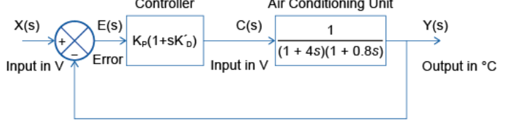
I have been given the task as a tranee control engineer to design a closed-loop controller an air conditioning unit so that it has the following properties: Maximum overshoot: 10% , maximum time to reach 99% of steady state: 10 seconds, Maximum steady-state error: 10%
i have to design a PD controller in a closed-loop system - The steady state error is 1/(1+KP) so i need KP to be at least 9 to meet the brief.
I need to choose the K’D parameter so that the zero that it produces is placed somewhere between the open-loop pole, therefore put it at s = -1. I've to assume the closed loop transfer function for this system fits the standard form of a second order response when performing calculations of natural frequency, damping ratio and gain and for plotting the unit step response.
I have added the example diagram of a closed-loop system with PD control i was supplied


Step by stepSolved in 4 steps with 13 images


- 316 and controller C(s), as shown in the 3. Consider a unity-feedback control system with plant G(s) following figure. Reference Error Controller Plant r(t) e(t) u(t) y(1) C(s) G(s) (a) Determine the poles, zeros, order, type, relative degree, and de gain of the plant G(s) and show using the Routh-Hurwitz criterion that G(s) is not stable. = Kp stabilize the plant G(s)? If so, find the values of Kp that are (b) Can a P controller C(s) necessary and sufficient. (c) Show using the Final Value Theorem that the system with the P controller from (b) can track a unit-step reference r(t) = 1 with zero steady-state error limo e(t) = 0. (d) Show that it however cannot track a unit-ramp reference r(t) =t with zero steady-state error. Can the error be made arbitrarily small with Kp without losing stability? (e) Can a PI controller C(s) = Kp + AL stabilize the plant G(8) and, at the same time, yield zero steady-state error to both unit-step and unit-ramp references? If so, find the values of Kp…arrow_forwardExplain the fundamental differences between open-loop and closed-loop control systems. Provide examples of each and discuss the advantages and limitations of both approaches.arrow_forwarddetermine Vo:arrow_forward
- In swimming pools and water tanks, the water level needs to be controlled. To manage the water level, a water level controller device is used. The aim of water level controller is to adjust water flow and improve the functioning. For the water level closed loop system shown in figure Q4, analyze the following basic components of the system: (1) Controlled variable (ii) Reference variable (ii) Comparison element (iv) Error signal (v) Control unit Hollow ball Lever Water input Pivotarrow_forwardExplain the concept of transfer functions and their relevance in control systems.arrow_forwardThe error signal that feeds the controller in a feedback control loop was recorded at various times, shown in Table 1. In open-loop mode, the magnitude of the signal feeding to the actuator was 12.0 mA at the instant when the controller was switched on at time zero.The steady-state process gain for the actuator, main process and sensor, considered as a single process, is 5.0 gpm/mA (a) Consider a P-only controller to be switched on and the proportional gain is0.3 mA/gpm. What is the magnitude of the control signal sent to the actuator at 10 seconds? (b) Consider a PI controller to be switched on; the proportional gain and inte-gral time are 0.3 mA/gpm and 6.0 seconds, respectively. Estimate the magnitude of the control signal sent to the actuator at 25 seconds. (c) What do you think the controlled variable and its corresponding desired set point are?arrow_forward
- i.A closed-loop control system is created using a proportional controller. Show that such a system has a steady state error of 1/(1+Kp) and therefore the steady state error condition can be achieved with a proportional gain of 9 or more.arrow_forwardQ2:A common actuator in control systems is the DC motor, determine the transfer function of the armature-controlled DC motor system described below. Represent the transfer function in terms of the input voltage (V) and the output angular velocity 0. Where T = Ki and e = Kė. Suter winding Angk Bearings R Bruss Armature P circuit Rotor Fixed fieldarrow_forwardV3arrow_forward
- Introductory Circuit Analysis (13th Edition)Electrical EngineeringISBN:9780133923605Author:Robert L. BoylestadPublisher:PEARSON
 Delmar's Standard Textbook Of ElectricityElectrical EngineeringISBN:9781337900348Author:Stephen L. HermanPublisher:Cengage Learning
 Programmable Logic ControllersElectrical EngineeringISBN:9780073373843Author:Frank D. PetruzellaPublisher:McGraw-Hill Education
  Fundamentals of Electric CircuitsElectrical EngineeringISBN:9780078028229Author:Charles K Alexander, Matthew SadikuPublisher:McGraw-Hill Education
 Electric Circuits. (11th Edition)Electrical EngineeringISBN:9780134746968Author:James W. Nilsson, Susan RiedelPublisher:PEARSON
 Engineering ElectromagneticsElectrical EngineeringISBN:9780078028151Author:Hayt, William H. (william Hart), Jr, BUCK, John A.Publisher:Mcgraw-hill Education,