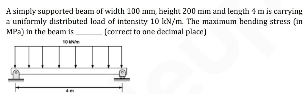
A simply supported beam of width 100 mm, height 200 mm and length 4 m is carrying a uniformly distributed load of intensity 10 kN/m. The maximum bending stress (in MPa) in the beam is (correct to one decimal place) 10 kN/m 4 m


Q: A beam is subjected to equal bending moments of M, = 52 kip-ft. The cross-sectional dimensions are…
A:
Q: Consider the given beam and loading where P= 78 kN/m. (For W250 x 8o, S= 983 x 103 mm3.) 12 kN m D…
A: Draw the free-body diagram of the beam. Apply force equilibrium in a vertical direction.…
Q: A beam of rectangular section of 12 cm × 20 cm is simply supported over a span of 12 m. It is acted…
A: Given data: - The width of the beam is b = 12 cm. The height of the beam is d = 20 cm. The load…
Q: A wood beam carries the loading shown in the figure. Calculate the magnitude of the bending stress…
A:
Q: A solid rectangular homogeneous section (total length = 7.2m) is simply supported, where b = 50 mm…
A: Draw the schematic diagram of the beam representing the forces.
Q: Determine the vertical displacement, in mm, of point C of the beam shown in the figure below. The…
A:
Q: A vertical loads of 400 N acts at the end of a horizontal rectangular cantilever beam 2 m long and…
A:
Q: Flexural Members The cross-sectional dimensions of a beam are given. If the maximum allowable…
A: Given Data: Maximum bending stress, 230 MPa
Q: For the beam shown, calculate the magnitude of the bending stress (in psi) at a point 1.14 in from…
A:
Q: For the beam shown, calculate the magnitude of the bending stress (in psi) at the top of the beam on…
A:
Q: Determine the vertical displacement, in mm, of point C of the beam shown in the figure below. The…
A:
Q: A wood beam carries the loading shown in the figure. calculate the maximum bending stress (in Pa) if…
A:
Q: times larger than in steel shaft. Q1) For the section shown aside, if the bending stress at point B…
A:
Q: A beam with a solid homogeneous rectangular section is simply supported at A and B. A concentrated…
A: Given Data: The magnitude of load, F=150 kN
Q: A beam with a solid homogeneous rectangular section is simply supported at A and B. A concentrated…
A:
Q: For the simply supported beam subjected to the loading shown, sketch the shear force diagram.…
A:
Q: A beam with a solid homogeneous rectangular section is simply supported at A and B. A concentrated…
A:
Q: For the beam shown, calculate the magnitude of the bending stress (in psi) at a point 1.14 in from…
A:
Q: A beam with a solid homogeneous rectangular section is simply supported at A and B. A concentrated…
A:
Q: Lets consider a cantilevered beam subjected to a uniform trectangular) load with intensity 4 kN/m.…
A: Shear force diagram represents shear force at every section of the beam..Shear force at any…
Q: For the beam shown, calculate the magnitude of the bending stress (in psi) at the bottom of the beam…
A:
Q: 10 kN/m |2m 2m 2m 6m 6m 2. A compound beam is pin connected at E and Fas shown above. a. Determine…
A: For solution refer below images.
Q: A uniformly distributed load of 321 Ib/ft is carried by a simply supported beam span. The beam is a…
A:
Q: Draw the shear and bending moment diagrams of the beams loaded as shown in the figures below. Round…
A:
Q: A beam with a solid homogeneous rectangular section is simply supported at A and B. A concentrated…
A:
Q: Determine the internal normal force, shear force, and bending moment at point C in the beam. 5 kN/m…
A:
Q: 1. According to the most unfavorable principle, loading the following moment influence line by using…
A: Write the given data. For L0⩽5 then Pk=270 kNFor 5<L0⩽50 m then Pk=2L0+130 kNFor L0≥50 then…
Q: A wood beam carries the loading shown in the figure, calculate the magnitude of the bending stress…
A:
Q: 15m 20 MFa 1. If the maximum bending stress in the shown beam is (Omax=20 MPa),the normal stress at…
A: A moment is a movement of the body when a body is rotating on an axis. The moment is also known as…
Q: 6. 6 The bending section modulus of a hollow cylindrical beam with an outer diameter of D and an…
A:
Q: A solid rectangular homogeneous section (total length = 7.2m) is simply supported, where b = 50 mm…
A:
Q: For the same beam as in Question 1, if the applied moment Mz on the cross section is 1.0 kN.m, the…
A:
Q: A beam with a solid homogeneous rectangular section is simply supported at A and B. A concentrated…
A:
Q: For the beam shown, calculate the magnitude of the bending stress (in psi) at a point 0.63 in from…
A:
Q: N for Newton, m for meter, mm for millimeter, N/(mm^2) for Stress, mm^2 or m^2 for Area, mm^4…
A: Since we only answer up to 3 sub-parts, we’ll answer the first 3. Please resubmit the question and…
Q: A wood beam carries the loading shown in the figure. calculate the magnitude of the bending stress…
A:
Q: 1. For the prismatic beam and loading shown in Fig: Q1, using singularity functions write equations…
A:
Q: A beam with a solid homogeneous rectangular section is simply supported at A and B. A…
A:
Q: Q5: A 8 m long simply supported steel beam with a hollow rectangular cross-section carries a 20 kN…
A:
Q: For the beam shown, calculate the magnitude of the bending stress (in psi) at the bottom of the beam…
A:
Q: A wood beam carries the loading shown in the figure. calculate the maximum bending stress (in Pa) if…
A:
Q: A wide flange beam as shown below is subjected to a shear force V. Using the dimensions of the cross…
A:
Q: Calculate the maximum bending moment that the beam experiences and give your answer in kilonewton…
A:
Q: A beam of size 150 mm wide, 250 mm deep carries a uniformly distributed load of w kN/m over entire…
A: For the given data and assuming it's a simply supported beam, it's configuration loading diagram…
Q: A uniformly distributed load of 226 Ib/ft is carried by a simply supported beam span. The beam is a…
A: Given data :- b =4.8 in h=5.7 in t =2.6 in
Q: 1. Determine the maximum positive bending moment in the beam in kN-m. 2. Determine the maximum…
A:
Q: is three times larger than in steel shaft. Q1) For the section shown aside, if the bending stress at…
A:
Q: A solid rectangular homogeneous section (total length = 7.2m) is simply supported, where b = 50 mm…
A:
Q: A beam is subjected to equal bending moments of M, = 3000 N-m. The cross-sectional dimensions are b…
A:
Q: For the beam shown, calculate the magnitude of the bending stress (in psi) at a point 0.65 in from…
A:

Step by step
Solved in 2 steps with 2 images


- A rectangular beam with semicircular notches, as shown in part b of the figure, has dimensions h = 120 mm and h1= 100 mm. The maximum allowable bending stress in the plastic beam is emix = 6 M Pa, and the bending moment is M = 150 N · m. Determine the minimum permissible width bminof the beam..10 A built-up bourn supporting a condominium balcony is made up of a structural T (one half of a W 200 x 31.3) for the top flange and web and two angles (2 L 2 / b / 6.4. long legal back-lo-backl lot the bottom flange and web. as shown. The beam is subjected to a bending moment .1/ having its vector at an angle ft lo the z axis (see figure). Determine the or ion ta I ion of the neutral axis and calculate the maximum tensile stress ir, and maximum compressive stress tr. in ".he beam. .Assume that 9 = 30°andM = 15 kN · m. Use the numerical properties: c =4.111mm, c2 =4.169 mm, of = 134 mm, I, = 76 mm, A = 4144 mm 3 =3.88 X 106 mm 4, and = 34.18 X 10 mm 4.The cross section of a rectangular beam having a width b and height h is shown in part a of the figure. For reasons unknown to the beam designer, it is planned to add structural projections of width b/9 and height d/9 the top and bottom of the beam (see part b of the figure). For what values of d is the bending-moment capacity of the beam increased? For what values is it decreased?
- A rectangular beam with semicircular notches, as shown in part b of the figure, has dimensions h = 0,88 in. and h1 = 0.80 in. The maximum allowable bending stress in the metal beam is emax = 60 ksi, and the bending moment is M = 600 lb-in. Determine the minimum permissible width bminof the beam.A two-axle carriage that is part of an over head traveling crane in a testing laboratory moves slowly across a simple beam AB (sec figure). The load transmitted to the beam from the front axle is 2200 lb and from the rear axle is 3800 lb. The weight of the beam itself may be disregarded. Determine the minimum required section modulus S for the beam if the allowable bending stress is 17,0 ksi, the length of the beam is 18 ft, and the wheelbase of the carriage is 5 ft. Select the most economical I-beam (S shape) from Table F-2(a), Appendix F.A simple beam ACE is constructed with square cross sections and a double taper (see figure). The depth of the beam at the supports is dAand at the midpoint is dc= 2d 4. Each half of the beam has length L. Thus, the depth and moment of inertia / at distance x from the left-hand end are, respectively, in which IAis the moment of inertia at end A of the beam. (These equations are valid for .x between 0 and L, that is, for the left-hand half of the beam.) Obtain equations for the slope and deflection of the left-hand half of the beam due to the uniform load. From the equations in part (a), obtain formulas for the angle of rotation 94at support A and the deflection Scat the midpoint.
- A simple beam A B of a span length L = 24 ft is subjected to two wheel loads acting at a distance d = 5 ft apart (see figure). Each wheel transmits a load P = 3.0 kips, and the carriage may occupy any position on the beam. Determine the maximum bending stress Gmaxdue to the wheel loads if the beam is an I-beam having section modulus S = 16.2 in3. If d = 5 ft. Find the required span length L to reduce the maximum stress in part (a) to 18 ksi. If L = 24 ft, Find the required wheel spacing s to reduce the maximum stress in part (a) to 18 ksi.A rectangular beam with notches and a hole (see figure) has dimensions h = 5.5 in., h1= 5 in., and width b = 1.6 in. The beam is subjected to a bending moment M = 130 kip-in., and the maximum allowable bending stress in the material (steel) is emax = 42,000 psi. What is the smallest radius Rminthat should be used in the notches? What is the diameter dmixof the largest hole that should be drilled at the mid height of the beam?A beam of length L is designed to support a uniform load of intensity q (see figure). If the supports of the beam are placed at the ends, creating a simple beam, the maximum bending moment in the beam is qL2/8. However, if the supports of the beam are moved symmetrically toward the middle of the beam (as shown), the maximum bending moment is reduced. Determine the distance a between the supports so that the maximum bending moment in the beam has the smallest possible numerical value. Draw the shear-force and bending-moment diagrams for this condition. Repeat part (a) if the uniform load is replaced with a triangularly distributed load with peak intensity q0= q at mid-span (see Fig. b).
- A frame ABCD is constructed of steel wide-flange members (W8 x 21; E = 30 x ID6 psi) and subjected to triangularly distributed loads of maximum intensity q0acting along the vertical members (see figure). The distance between supports is L = 20 ft and the height of the frame is h = 4 ft. The members are rigidly connected at B and C. Calculate the intensity of load q0 required to produce a maximum bending moment of 80 kip-in. in the horizontal member BC. If the load q0 is reduced to one-half of the value calculated in part (a), what is the maximum bending moment in member BC? What is the ratio of this moment to the moment of 80 kip-in. in part (a)?The cross section of a sand wie h beam consisting of aluminum alloy faces and a foam core is shown in the figure. The width b of the beam is 8.0 in, the thickness I of the faces is 0.25 in., and the height hcof the core is 5.5 in. (total height h = 6.0 in). The moduli of elasticity are 10.5 × 10⁶ psi for the aluminum faces and 12.000 psi for the foam core. A bending moment M = 40 kip-in. acts about the z axis. Determine the maximum stresses in the faces and the core using (a) the general theory for composite beams and (b) the approximate theory for sandwich beams.A C 200 x 17.1 channel section has an angle with equal legs attached as shown; the angle serves as a lintel beam. The combined steel section is subjected to a bending moment M having its vector directed along the z axis, as shown in the figure. The cent roi d C of the combined section is located at distances xtand ycfrom the centroid (C1) of the channel alone. Principal axes yl and yvare also shown in the figure and properties Ix1,Iy1and 0pare given. Find the orientation of the neutral axis and calculate the maximum tensile stress exand maximum compressive stress if the angle is an L 76 x 76 x 6.4 section and M = 3.5 kN - m. Use the following properties for principal axes for the combined section:/^, = 18.49 X 10⁶ nrai4,/;| = 1.602 X 106 mm4, ep= 7.448*(CW),_r£ = 10.70 mm,andvf= 24.07 mm.