Statémént A single line diagram of a power system is shown in Fig.3.1. All the sequence reactances of the power system components are depicted in per unit on 20 MVA base, 110KV (L-L) in transmission circuit. If a single line to ground fault occurs on phase a through a reactance of 150 ohm at F, determine the current in ampere fed into the fault. The fault point F is assumed to be at 65% of transmission line length from the bus bar connected to generators A and B. 20 MVA |Xa~X;~ j ®.1 Xy~j 0.35 n 1I KV X;=j0.3 X-j0.3 Xy-j0.05/ 20 MVA X,=j0.25 X;=j0.25 Xy=j0.05 110 KV Transmission X-X,-X-J 0.1 X-X=X¢=j 0.1 circuit D |Xr-Xx= j®.1 Xx=j 0.35 X-X-Xrj 0.1 X-X-X 0.1
Statémént A single line diagram of a power system is shown in Fig.3.1. All the sequence reactances of the power system components are depicted in per unit on 20 MVA base, 110KV (L-L) in transmission circuit. If a single line to ground fault occurs on phase a through a reactance of 150 ohm at F, determine the current in ampere fed into the fault. The fault point F is assumed to be at 65% of transmission line length from the bus bar connected to generators A and B. 20 MVA |Xa~X;~ j ®.1 Xy~j 0.35 n 1I KV X;=j0.3 X-j0.3 Xy-j0.05/ 20 MVA X,=j0.25 X;=j0.25 Xy=j0.05 110 KV Transmission X-X,-X-J 0.1 X-X=X¢=j 0.1 circuit D |Xr-Xx= j®.1 Xx=j 0.35 X-X-Xrj 0.1 X-X-X 0.1

Power System Analysis and Design (MindTap Course List)
6th Edition
ISBN:9781305632134
Author:J. Duncan Glover, Thomas Overbye, Mulukutla S. Sarma
Publisher:J. Duncan Glover, Thomas Overbye, Mulukutla S. Sarma
Chapter3: Power Transformers
Section: Chapter Questions
Problem 3.49P: Consider the single-Line diagram of a power system shown in Figure 3.42 with equipment ratings...

Related questions

Concept explainers
Three-Phase Transformers
Three-segment transformers are a type of transformer used to transform voltages of electrical systems into three ranges. Two type transformers are shell-type transformer and core type transformer. In brief, it could be described because of the exquisite kinds of configurations.
Transformer
Ever since electricity has been created, people have started using it in its entirety. We see many types of Transformers in the neighborhoods. Some are smaller in size and some are very large. They are used according to their requirements. Many of us have seen the electrical transformer but they do not know what work they are engaged in.
Question
Transcribed Image Text:Statement
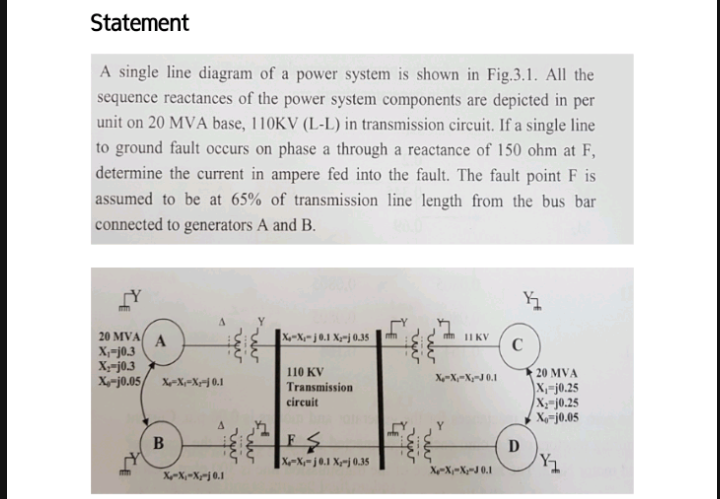
A single line diagram of a power system is shown in Fig.3.1. All the
sequence reactances of the power system components are depicted in per
unit on 20 MVA base, 110KV (L-L) in transmission circuit. If a single line
to ground fault occurs on phase a through a reactance of 150 ohm at F,
determine the current in ampere fed into the fault. The fault point F is
assumed to be at 65% of transmission line length from the bus bar
connected to generators A and B.
20 MVA
|X-~X;~j ®.1 Xy~j 0.35
II KV
A
X;-j0.3
X;-j0.3
X-j0.05/
110 KV
Transmission
20 MVA
X,-j0.25
X;=j0.25
Xo-j0.05
X-X;=Xy¬J 0.1
X-X,=Xx=j 0.1
circuit
B
D
|Xr-Xx= j®.1 Xx=j 0.35
X-X-X-J 0.1
X-X,~Xg~j 0,1
Expert Solution
This question has been solved!
Explore an expertly crafted, step-by-step solution for a thorough understanding of key concepts.

Step by step
Solved in 5 steps with 11 images

Knowledge Booster


Learn more about
Need a deep-dive on the concept behind this application? Look no further. Learn more about this topic, electrical-engineering and related others by exploring similar questions and additional content below.Recommended textbooks for you
Power System Analysis and Design (MindTap Course …
Electrical Engineering
ISBN:
9781305632134
Author:
J. Duncan Glover, Thomas Overbye, Mulukutla S. Sarma
Publisher:
Cengage Learning
Power System Analysis and Design (MindTap Course …
Electrical Engineering
ISBN:
9781305632134
Author:
J. Duncan Glover, Thomas Overbye, Mulukutla S. Sarma
Publisher:
Cengage Learning