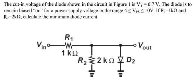
The cut-in voltage of the diode shown in the circuit in Figure 1 is Vy = 0.7 V. The diode is to remain biased "on" for a power supply voltage in the range 4 < Vps < 10V. If R;=lkN and R2=2kQ, calculate the minimum diode current- R1 Vino Vout 1 kQ 2 ko D2 R2


Q: The four diodes used in a bridge rectifier circuit have forward resistances which may be considered…
A:
Q: Problem 1 In the following circuit, the Zener diode works in the reverse bias region and the current…
A: Brief description : Zener diode is a special type of heavily doped PN junction diode. The doping…
Q: Draw the voltage transfer characteristic for the circuit shown in Figure Q4. Assume that V₂ = 0.7V…
A:
Q: onsider the circuit shown in Figure 2 below. Here, I, = 1.2 × 10⁻¹⁶ A and R1 = 1 kN. %3D R1 în Vd Vx…
A:
Q: A silicon diode at room temperature has a cross sectional area of 10μm². It is doped such that: Na =…
A:
Q: Under controlled conditions a diode's current is modelled by the equation : Question 1 I, =…
A: Given Under controlled conditions a diode's current is modelled by the equation : ID=Is…
Q: The specifications of the diode are given as VD=D0.8V at a temperature of 300K with a leakage…
A:
Q: In the circuit of Figure 1.c, the voltage source is equal to V = 5 V and the load resistor is equal…
A: The calculation of diode current is as fallows
Q: Time left 0:32 If the voltage at the cathode of a diode is -1 V, and the anode is connected to the…
A:
Q: For the series diode configuration of Fig.a , employing the diode characteristics of Fig.b,…
A: Given: Brief description: In the given question they have mentioned an electrical circuit having…
Q: If the current I is 2mA then find the temperature at which the diode operates. The cut-in voltage of…
A: Given parameters: Current in the circuit, I = 2 mA The cut-in voltage of the diode, Vc = 0.6 V…
Q: The equation for the current flowing through a qV – E, I = Ae kT In equation A, k, q and Eg are…
A:
Q: The reverse-bias saturation current of the diode in the circuit below is 10-14 A. The current…
A: Given : saturation current Is = 10-14 A Current through diode ID = 1.2 mA To find the closest value…
Q: Q3: A.C. voltage with peak value (Vm-20V) is connected in series with silicon diode and load (R= 500…
A: 1... For silicon Diode. The forward voltage drop of silicon diode is 0.7V. The diode will be forward…
Q: R Q19. The minimum input voltages that can be regulated by the zener diode in figure 5. Vz=5.1 V at…
A:
Q: lhe eireuit of Figure T.c, the voltage source is equal to V = 5 V and the load sistor is equal to R…
A:
Q: 1.In p-n junction diode, the forward bias current is very small as compared to the reverse bias…
A: P-N junction diode: In P-N junction diode, the p side is has excess of holes while the n side has…
Q: Question2: At a temperature of 308 K, a certain junction diode has in = 0.1 mA for vD = 0.6 V.…
A:
Q: Q.4b Consider the diode circuit shown below. Assume both diodes are silicon-based diodes with…
A:
Q: V, Consider the peak detector circuit on the right. The input v, is 5V for t=0. Determine the…
A: Given: Brief description: In the above given question they have mentioned an electrical circuit…
Q: Q3. In the circuit shown below, find the diode voltage VD and the supply voltage V such that the…
A:
Q: Calculate the reverse current of P-N diode, if a forward current of 10mA is flowing through it if…
A:
Q: 2.3 The reverse recovery time of a diode is trr both (a) the storage charge QRR and (b) the peak…
A: QRR v/s rate of fall of the diode and IRR V/S rate of fall of the diode is plotted determined
Q: Froblem 2: Assume the capacitor is initially discharged with v-(0) = 0V. Sketch the capacitor…
A:
Q: Under controlled conditions a diode's current is modelled by the equation : Question 1…
A: Given diode current equation is ID=IsekV-1 Where V is diode forward bias voltage. Is is diode…
Q: Q.5 (a) Referring to the circuit in Figure B.3, diode, Di is Silicone with VD = 0.7V. UTM S UTM S…
A: In this question, Half wave Rectifier is given Find the all unkown parameters and draw the output…
Q: 4. (a) Calculate the ideal reverse saturation current density in a silicon p-n junction diode. The…
A: Given data, Na=5×1016cm-3Nd=5×1016cm-3ni=9.65×109cm-3Dn=21cm2/secDp=10cm2/secτn=τp=5×10-7seconds
Q: the circuit shown below, if the diode current is given by I = 1,(eva/VT -1), where Vr = 25 mV, and…
A: In this question , we will find input voltage of opamp..
Q: A germanium pn junction diode was fabricated on a wafer with doping concentration of 7.8 x 105 cm3.…
A: We need to find barrier potential and depletion width and current for given diode .
Q: 3. (a) Consider the circuit shown. The value of R1 is reduced to R1 = 10kohms and the cut-in voltage…
A: Given Basics of diode
Q: • Example 2 Example 1 For the circuit shown in Figure 1, find the diode current (Ip), the diode…
A: Draw the figure and find the voltage across resistor and diode voltage.
Q: U3: A.C. voltage with peak value (Vm 20V) is connected in series with silicon diode an and load…
A:
Q: PART I: Theory Question 1: Consider a silicon diode with reverse saturation current of Is = 2 pA. a.…
A:
Q: Which of the following indicates the correct rms value of the diode current for a 1-o full bridge…
A:
Q: Can you solve this question by explaining your solution step by step and giving details on the…
A:
Q: 3) In a p-n junction diode, the reverse saturation current (I,) is . . diode forward-bias voltage is…
A:
Q: Determine the voltage and the current of the diode in: a) First Approximation b.) Second…
A:
Q: Find the width of the depletion layer in a germanium junction diode which has the following…
A:
Q: Question:1 A diode whose internal resistance (forward biased) is 20 2 is to supply power to a 1000 2…
A: We are authorized to answer three subparts at a time, since you have not mentioned which part you…
Q: RL = 1kN. Assuming the cut in voltage of diode=0.7V, solve for the following: (i) total peak output…
A: Since you have asked multiple questions in a single request, we will be answering only the first…
Q: Diodes D1, D2, D3 and D4 are identical Silicon diodes with forward voltage drop of 0.7 volts.…
A: As per Bartleby policy we can not solve all parts at a time. I am solving 3 parts for you. please…
Q: Consider the peak detector circuit on the right. The input v, is 5V for t=0. Determine the…
A: According to the question, for the circuit shown below we need to find
Q: R1 L1 D1 400 200m D V1 R2 1600 10 he switch is closed for t<0 and opens at t=0. Determine the state…
A:
Q: Check understanding Known Quantities: Vs = 12 V: Vn = 7 V; R, = 5 0; R; = 10 2: R, = 10 Sn Find: The…
A: Initially assume Diode is OFF
Q: trả 50 Ω D1 D2 50 Ω của 2.5 V(+ 50 Ω. Assuming an ideal offset model with VON = 0.7V for each diode,…
A:
Q: Q. 12: A diode is a device that conducts in one direction only. Figure (a) shows the symbol for a…
A: This question is based on the concept of switching a diode and the voltage division rule of a…
Q: (a) Sketch the output voltage, v.out for the circuit shown in Figure 2.1 clearly indicating time…
A:

Step by step
Solved in 2 steps with 2 images


- How is a solid-state diode tested? Explain.a) To what value R must be adjusted in the following circuit to make IZ = 70 mA. Assume VZ =20 V at 65 mA and ZZ = 23 Ω. What is the Zener voltage at 70o C, if it has a positive TC of 0.08 %/oC.? b) Using a Complete diode model, find the diode current (ID), diode voltage (VD), and output voltage (Vo) for the diode circuit shown below. Given that: Vs = 20 V, RL=3 kΩ , Barrier Potential VF = 0.3 V , and r’d = 70 Ω. If the diode was reversed and IR = 200 µA, Determine the diode reverse voltage (VR)Since R1=4.51 Kohm, R2=1.19 Kohm R3=2.74Kohm R4=5.60Kohm VCC=23.00V and diode silicon in the circuit given in the figure, find the current passing through the diode in mA
- Given the schematic below, assume D1 and D2 are silicon with forward voltages of 0.7V. Find the following (with solutions) a) Conditions required wherein none of the diodes are conducting b) If both diodes are not conduction, what is Vo? Express in terms of Vi c) Plot the overall relationship of Vo and Vi in the coordinate system shown below. Remember, you are to plot the transfer characteristics of the circuit.2b) A regulator curcuit needs to be designed with an input power supply which has a nominal value of V_PS=20 V and can vary by ± %25 and nominal output voltage of 10 volts. For this purpose a zener diode is employed with specifications given; power rating of 1 W, 10V drop at Iz=25 mA, output load current is to vary between I(subscript L)=0-20 mA and zener resistance of r_Z=5Ω i) If the minimum Zener current is to be I_Z=5 mA, determine the required R_S ii) Determine the maximum variation in output voltage iii) Determine the regulation percentFor the half-wave rectifier circuit shown, the diode is not ideal and is modeled as an ideal voltage source of value Vf= =0.65V in series with an ideal diode. Vin= 2sin(2π10t) and R= 470Ω. What is the magnitude of the diode current at time t=60mst=60ms? 2- At what time between 0and T/4 seconds is the magnitude of the diode current equal to 2.66mA? Tis the period of Vin Enter your answer in milliseconds
- Q1: In this Zener diode regulator, the source voltage varies from 6 V to 14 V. Assume that the load current varies between 1 mA and 35 mA, and that the diode is an ideal 4 V Zener diode. What is the largest allowable resistance that will ensure the load voltage remains constant with variations in load current and source voltage? Please enter your answer to 3 significant figures. Q2: Given the circuit design for a Zener diode regulator in the Ques 1, what is the maximum power that will be dissipated by the Rs resistor? You are told that the source voltage Vs varies from 6 V to 11 V, the load current il varies between 2 mA and 45 mA, and the diode is an ideal 3 V Zener diode. You will need to recalculate the maximum allowable resistance Rs with your new values, as part of this question. Please enter your answer to 3 significant figures, and in Watts.For the ideal-diode clipper circuit given below, VS = 12.sinωt V. Determine the output voltage Vout and sketch this function. Remove the short circuit between points x and y, and replace it with a 2kΩ Resistor. Find the range of values of VS for; D1 and D2 are OFF D1 is ON and D2 is OFF D1 is OFF and D2 is ON Is it possible for both D1 and D2 to be ON?For the half-wave rectifier circuit shown, the diode is not ideal and is modeled as an ideal voltage source of value Vf= 0.65V in series with an ideal diode. Vin= 5sin(2π100t) and R =510Ω. What is the output voltage at time t=24mst=24ms? 2- For the same circuit as in Question 1, what is the output voltage at time t=35.4ms t=35.4ms? Enter your answer in volts 3- For the same circuit as in Question 1, what is the magnitude of the diode current at time t=12mst=12ms? Enter your answer in mA without units.
- While constructing a Bridge rectifier, the designer mistakenly has swapped the terminals of D3 as shown in the figure below, where • Diode D3 is damaged so that it is always open circuit regardless of the applied voltage. • vs(t) is a sinusoidal signal with a peak value (Vs = 5 V). • Diodes are modelled using the constant voltage model with VDO = 0.7 V • The ac line voltage has an rms value of 120 V and a frequency (f) = 60 Hz • The resistance RL = 10 kohm. a) Calculate the transformer turns ratio (N1/N2) if vs(t) is obtained from the secondary side of the transformer whose primary side is connected to the ac line voltage (which has a 120 V rms value). b) Plot in the same graph the input signal vs(t) and the output signal vout(t) (show all details including amplitudes, time instances, etc.) c) Calculate the rms values of the output signal vout(t). (hint: sin2 (x) = 0.5(1- cos(2x))) d) If a capacitor C = 3.58 µF is connected across R = 10 kohm, repeat (b) in a new graph e) With the…While constructing a Bridge rectifier, the designer mistakenly has swapped the terminals of D3 as shown in the figure below, where • Diode D3 is damaged so that it is always open circuit regardless of the applied voltage. • vs(t) is a sinusoidal signal with a peak value (Vs = 5 V). • Diodes are modelled using the constant voltage model with VDO = 0.7 V • The ac line voltage has an rms value of 120 V and a frequency (f) = 60 Hz • The resistance RL = 10 kohm. a) Calculate the transformer turns ratio (N1/N2) if vs(t) is obtained from the secondary side of the transformer whose primary side is connected to the ac line voltage (which has a 120 V rms value). b) Plot in the same graph the input signal vs(t) and the output signal vout(t) (show all details including amplitudes, time instances, etc.) Please plot the graph. c) Calculate the rms values of the output signal vout(t). (hint: sin2 (x) = 0.5(1- cos(2x))) d) If a capacitor C = 3.58 µF is connected across R = 10 kohm, repeat (b) in a new…Apply each of diode approximations given the following parameters D`:rB= 2 ohms, rR= 220 kilohms: Si, rB = 5 ohms, rR= 560 kilo ohms Determine the current flowing through D1, D2 AND R2, R3, THE VOLTAGE ACROSS R3 SOLVE IN THREE DIODE APRROXIMATIONS