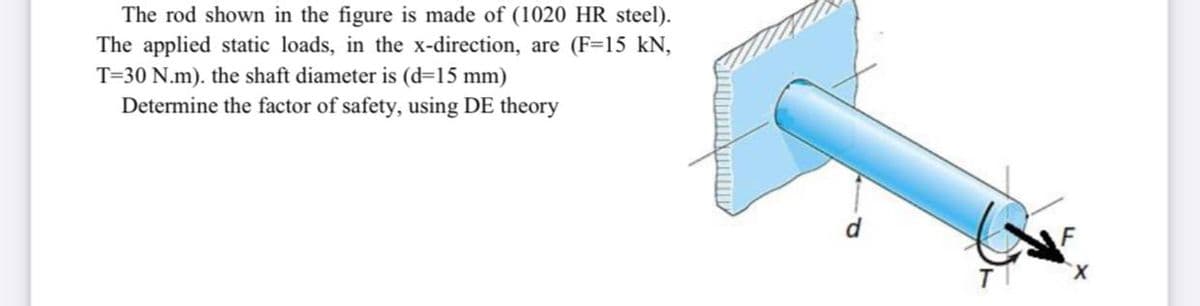
The rod shown in the figure is made of (1020 HR steel). The applied static loads, in the x-direction, are (F=15 kN, T=30 N.m). the shaft diameter is (d=15 mm) Determine the factor of safety, using DE theory


Q: A circular bar AB with ends fixed against rotation has a hole extending for half of its length (sec…
A:
Q: Q1: Find the Diameter of the shaft made of A cold-drawn steel. Assume that ultimate stress is 370…
A: Given: The ultimate stress = 370 MPa The factor of safety, n = 3 The tension in the loose side, T2 =…
Q: A bracket (shown in figure) is rigidly mounted on wall using four rivets. Each rivet is 6 mm in…
A:
Q: A transmission shaft, supporting two pulleys A and B and mounted between two bearings C, and C, is…
A: Given data as per questionSut=600 N/mm2, Syt=380N/mm2, kb=1.5, kt=1Calculate permissible shear…
Q: H.W.7: A pin-connected structure is supported as shown in Figure load P is applied. Bar (1) is made…
A: Given data Bar (1) made of brass [oy = 18,000 psi; E = 17 x 106 psi], length of L = 8.0 ft. Bar…
Q: The assembly shown in the figure consists of rod (1) and tube (2), both made of steel (E = 30,000…
A:
Q: 3) Figure - 3 illustrates a type of engineering chain used for conveying applications. All…
A:
Q: Figure shows a rotating shaft simply supported in ball bearings at A and D and loaded by a…
A: Given data: The endurance limit of the shaft, Se = 180 MPa. Fatigue stress concentration at…
Q: In the figure, the length L = 500 cm and the profile section is given, one end of which is fixed and…
A: Given data :- L = 500 m Yield stress = 300 daN/cm2 n= 0.25 Le = 2L E = 2100000 daN/cm2 Find :-…
Q: Q3/ Thickness of plate is 5mm and its yield stress is 630 MPa with endurance limit equals 225 MPa,…
A:
Q: a) The material is 2024-T4 aluminum with a yield strength of 47 ksi b) The rod length L=6 in and arm…
A:
Q: Two plates with a thickness of 35 mm, width of 160 mm, and length of 200 mm are joined together by a…
A: Given data: - Thickness of the plate, t=35 mm,Width of the plate, w=160 mm,Length of the plate,…
Q: LA load F of 500 N is applied in the negative x-direction on rod OA, and a load P of 200 N is…
A: Given: The load, F = 500 N The force at B, P = 200 N
Q: 35 The bolted connection shown in the figure is subjected to a tensile shear load of 90 kN. The…
A:
Q: A butt connection is shown in the following figure. Plates is Q235 steel; 8.8 Grade M16 high-…
A: Load bearing capacity Loadbearing capacity is the maximum ability of a structural member or…
Q: The figure below is subjected to a load fluctuating between Pmin and Pmax. Calculate the factor of…
A: Write the given values along with the suitable variables.
Q: A spring has a load of 50 lb with a spring index of 8. If the induced stress is 90ksi, determine the…
A:
Q: A rectangular plate of width b-40 mm and thickness s 20 mm has a hole with a diameter d=8 mm in the…
A: Given:b=40 mms=20 mmd=8 mmF=15000 NFor dw=840=0.2;From the graph:Kf=2.5Stress developed without…
Q: Circular steel bars will be used in the cage system in the figure. Accordingly, find the safety and…
A: The roller at D gives the vertical reaction and the hinge at G gives the horizontal and vertical…
Q: he bar shown in the following figure has a diameter of 20 mm and is subjected to a force P = 2750 N…
A: Given:d=20 mmP=2750 NF=14000 NSyt=480 MPaPoint A will be subjectd to tensile stress due to bending…
Q: Axial loads are applied with rigid bearing plates to the solid cylindrical rods shown in the figure.…
A:
Q: The figure below shows a symmetric T-section that is subjected to a linearly varying distributed…
A: In this problem, it is asking about the equivalent force of the given distributed load.
Q: Q2- The steel bar shown in the figure is subjected to a reversed axial load fluctuating between 28…
A:
Q: 100 100 600 A B. F=2000N 10
A: Given, Force = F = 2000 N Yield strength = σy = 355 N/mm2 Shear strength = τ = σy2 = 3552 = 177.5…
Q: 3 The A-36 steel rod BC as shown in Figure Q3 has a diameter of 50mm and is used as a strut to…
A:
Q: 3. A hollow cylindrical cast iron column 200 mm external diameter and 25 mm thick is 6 metres in…
A: Given, External diameter, Do=200mmThickness, t=25mmInternal diameter, Di=150mmLength of the column,…
Q: B. 5 m 3 m 30 mm -20 mm T20 mm The assembly above includes pin-connected column AB. Suppose that an…
A:
Q: Consider the steel arm assembly in the figure below that supports load R. Using the Coulomb-Mohr…
A: For solution refer below images.
Q: 3. A load P is supported by two concentric steel springs. Given: Inner Spring: 30 turns of 20-mm ø…
A: Given: A load P is supported by two springs. The number of turns of inner spring is, n1=30. The…
Q: m A 1016 100 27 KN 370 ↓ 180 180 [2 27 KN
A:
Q: A load of F of 3 kN is applied to the pulley shown in the figure. Plate 1 is attached to two plates…
A:
Q: The bell crack mechanism shown in Figure is in equilibrium for an applied load of F1 - 15KN at A and…
A: Answer: The magnitude of the resultant reaction force acting at point B is 30.5 kN.
Q: P1.6 Axial loads are applied with rigid bearing plates to the solid cylindrical rods shown in Figure…
A:
Q: 7. The strut illustrated in figure Q7 is built in at both ends. Determine the temperature…
A: Given:L=200 mmb=10 mmh=1 mmE=200 GPaμ=0.33α=11.7*10-6/°C
Q: A countershaft carrying two V-belt pulleys Is shown In the figure. Pulley A recelves power from a…
A:
Q: A solid circular rod with a diameter d= 18 mm is shown in Figure Q-3. The rod is made of an aluminum…
A: The diametral strain of the rod can be determined as, The longitudinal strain of the rod can be…
Q: The shaft shown the figure below, is supported by a bearing on the left end. The shaft also supports…
A: Given data,D=300
Q: What stresses are produced in the bolt and in the tube
A: Given: d1=0.5 in E1=30,000 ksi d2=1 in E2=16000 ksi t=0.125 in L=8 in nut is tightened an…
Q: A 2.5 cm x 7.5 cm steel beam with a length of 61 cm is subjected to a reversed load of 17.8 kN at…
A:
Q: The steel bar has the original dimensions shown in the figure. (Figure 1) It is subjected to an…
A: Given data: F=50 kN Need to determine the change in its length, the new height at section a-a, and…
Q: The cantilever bar in the figure is made from a ductile material and is statically loaded with Fy=…
A:
Q: A Component shown in figure below machined from a plate of steel C45 having ultimate strength as 630…
A:
Q: A rotating shaft of 25-mm diameter is simply supported by bearing reaction forces R, and R₂. The…
A: Given data: ● The load applied on the beam: W = 13 kN ● The diameter of the beam: d = 25 mm ● The…
Q: The bell-crank mechanism shown below is supported by a single-shear pin connection at B and a roller…
A: Find the maximum load
Q: Q3 The A-36 steel rod BC as shown in Figure Q3 has a diameter of 5X mm ( X is a last digit of your…
A:
Q: A rectangular filleted bar as shown in figure below is subjected to a fluctuating force F that…
A: The Answer is below
Q: What are the RA response and RB response?
A:
Q: Problem 5: 98.99) For the component shown in the figure. Where is the critical location? What steel…
A: Determine the ratio of Dd. Dd=2''1.25''=1.6 Determine the ratio of rd. rd=0.06''1.25''=0.048

Step by step
Solved in 2 steps with 2 images

- Repeat Problem 2.4-8, but assume that the bar is made of aluminum alloy and that BC is prismatic. Assume that P = 20 kim. L = 3 ft.t = 314 in., b1 2m.b 2.Sin.andElO.400ksi.Repeat Problem 2.3-18, but assume that the bar is made of copper alloy. Calculate the displacements SBand Scif P = 50 kips, L = 5 ft = 3/5 in., b1= 2.75 in., b2= 3 in., and E = 16,000 ksi.Two sections of steel drill pipe, joined by bolted flange plates at Ä are being tested to assess the adequacy of both the pipes. In the test, the pipe structure is fixed at A, a concentrated torque of 500 kN - m is applied at x = 0.5 m, and uniformly distributed torque intensity t1= 250 kN m/m is applied on pipe BC. Both pipes have the same inner diameter = 200 mm. Pipe AB has thickness tAB=15 mm, while pipe BC has thickness TBC= 12 mm. Find the maximum shear stress and maximum twist of the pipe and their locations along the pipe. Assume G = 75 GPa.
- A hollow circular tube A fits over the end of a solid circular bar B, as shown in the figure. The far ends of both bars are fixed. Initially, a hole through bar B makes an angle ß with a line through two holes in tube A. Then bar B is twisted until the holes are aligned, and a pin is placed through the holes. When bar B is released and the system returns to equilibrium, what is the total strain energy U of the two bars? (Let lAand lBrepresent the polar moments of inertia of bars A and B, respectively. The length L and shear modulus of elasticity G are the same for both bars.)A pinned-end strut of aluminum (E = 10,400 ksi) with a length L = 6 ft is constructed of circular tubing with an outside diameter d = 1 in. (sec figure). The strut must resist an axial load F = 4 kips with a factor of safety n = 2.0 with respect to the critical load. Determine the required thickness t of the tube.A rigid bar of weight W = 750 lb hangs from three equally spaced wires: two of steel and one of aluminum (see figure). The diameter of the wires is 1/8 in. Before they were loaded, all three wires had the same length. What temperature increase T in all three wires will result in the entire load being carried by the steel wires? (Assume Es= 30 × 106 psi, as= 6.5 × 10⁻⁶ /'F, and aa= 12 × 10-6F.)
- A magnesium-alloy wire of diameter d = 4mm and length L rotates inside a flexible tube in order to open or close a switch from a remote location (see figure). A torque Tis applied manually (either clockwise or counterclockwise) at end 5, thus twisting the wire inside the tube. At the other end A, the rotation of the wire operates a handle that opens or closes the switch. A torque T0 = 0.2 N · m is required to operate the switch. The torsional stiffness of the tube, combined with friction between the tube and the wire, induces a distributed torque of constant intensity t = 0.04N m/m (torque per unit distance) acting along the entire length of the wire. (a) If the allowable shear stress in the wire is T allow = 30 MPa, what is the longest permissible length Lmaxof the wire?The figure shows an idealized structure consisting of two rigid bars with pinned connections and linearly elastic rotational springs. Rotational stiffness is denoted ßR. Determine the critical load Pcrfor the structure.The device shown in the figure consists of a prismatic rigid pointer ABC supported by a uniform translational spring of stiffness k = 950 N/m. The spring is positioned a distance P = 165 nun from the pinned end A of the pointer. The device is adjusted so that, when there is no load P, the pointer reads zero on the angular scale. (a) If the load P = 11 N, al what distance .v should the load be placed so that the pointer will read ?? = 2.5° on the scale (see figure part a)? (b) Repeal part (a) if a rotational spring E1= kb-6 is added al A (see figure part b). (c) Lel.x = 7b/8.What is P maxif 0 cannot exceed 2"? Include spring krin your analysis. (d) Now, if the weight of the pointer ABC is known to be W =3N and the weight or the spring is Ws= 2.75 N, what initial angular position (Left in degrees) of the pointer will result in a zero reading on the angular scale once the pointer is released from rest? Assume P = kr=0. (e) If the pointer is rotated lo a vertical position (see figure part c), find the required load P applied at mid-height of the pointer that will result in a pointer reading of 0 = 2.5" on the scale. Consider the weight of the pointer W. in your analysis.
- A cable and pulley system at D is used to bring a 230-lcg pole (ACB) to a vertical position, as shown in the Figure part a. The cable has tensile force T and is attached at C. The length L of the pole is 6.0m, the outer diameter is d = 140 mm. and the wall thickness is t = 12 mm. The pole pivots about a pin at A in figure part b. The allowable shear stress in the pin is 60 MPa and the allowable bearing stress is 90 MPa. Find the minimum diameter of the pin at A in order to support the weight of the pole in the position shown in the figure part a.Solve the preceding problem if the internal pressure is 3,85 MPa, the diameter is 20 m, the yield stress is 590 MPa, and the factor of safety is 3.0. (a) Determine the required thickness to the nearest millimeter. (b) If the tank wall thickness is 85 mm, what is the maximum permissible internal pressure?A metal bar AB of a weight Ills suspended by a system of steel wires arranged as shown in the figure. The diameter of the wires is 5/64 in., and the yield stress of the steel is 65 ksi. Determine the maximum permissible weight W max for a factor of safety of 1.9 with respect to yielding.