
Computer Networking: A Top-Down Approach (7th Edition)
7th Edition
ISBN: 9780133594140
Author: James Kurose, Keith Ross
Publisher: PEARSON
expand_more
expand_more
format_list_bulleted
Related questions
Question
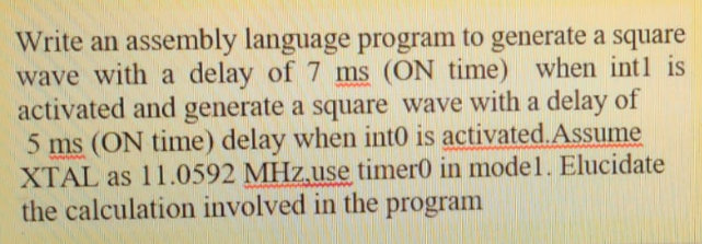

Transcribed Image Text:Write an assembly language program to generate a square
wave with a delay of 7 ms (ON time) when intl is
activated and generate a square wave with a delay of
5 ms (ON time) delay when into is activated.Assume
XTAL as 11.0592 MHz,use timero in model. Elucidate
the calculation involved in the
program
Expert Solution
This question has been solved!
Explore an expertly crafted, step-by-step solution for a thorough understanding of key concepts.

This is a popular solution

Trending nowThis is a popular solution!

Step by stepSolved in 2 steps

Knowledge Booster

Similar questions
- Assume we are writing a testbench for a sequential circuit that has three control inputs (cA, cB, cC) and a periodic clock (clk). If we define CLK_PERIOD as a localparameter with a value of 50 (nsec), write the testbench segment that would ensure all possible combinations of the control inputs were tested on a clock rising edge. This is can be done more elegantly if you define each time step in terms of the constant CLK_PERIOD. Your answer should include the statements that define clk, cA, cB, and cC over time. Hint: think of how you would show all combinations of three variables on a truth table and replicate that over time, where each combination is held over a timespan with a clock triggering edge.arrow_forwardUsing Logism Softwarel The most important and possible most difficult component to implement is the 8 bit arithmetic logic unit. Thefunctions of the ALU are shown in Table 1. The ALU should have 5 inputs (A-input, B-input, F0-input, F1-input, Finput) and 1 output (C-output). You will need to determine how many bits each input and output should have.Remember, you are designing an 8-bit microprocessor! . For example, to add the value on the A-bus8-bit ALUto the value on the B-bus, you can simply use an 8-bit adder. Explore the components in Logisim! Additionally,you can think about using a multiplexer to determine which ALU function will be performedarrow_forwardQUESTION 5 35 A convolutional circuit has three internal registers (s0, s1, and s2), and two outputs (c0 and c1), calculated as follows: c0=i+s2; c1=i+s0+s1. We are currently in state 110 and receive input 0. What is the output and next state? O c0=0; c1=0; next=011 O c0=1; c1=0; next=011 O c0=1; c1=1; next=011 O c0=0; c1=1; next=011 QUESTION 6 11 A convolutional circuit has three internal registers (S0, S1, and s2), and two outputs (c0 and c1), calculated as follows: c0=i+s0; c1=i+s1+s2. We are currently in state 110 and receive input 0. What is the output and next state? O c0=1; c1=1; next=011 O c0=0; c1=1; next=011 O c0=0; c1=0; next=011 O c0=1; c1=0; next=011 QUESTION 7 02 A convolutional circuit has three internal registers (s0, s1, and s2), and two outputs (c0 and c1), calculated as follows: c0=i+s0; c1=i+s0+s1. We are currently in state 011 and receive input 1. What is the output and next state? O c0=0; c1=1; next=101 O c0=0; c1=0; next=101 O c0=1; c1=0; next=101 O c0=1; c1=1;…arrow_forward
- Assume that an external clock signal is being fed into pin T0CKI (RA4). Write a C program touse Timer0 in 8-bit mode to count the pulses and display the state of the TMR0L count onPORTB. Start the count at 0x00 and stop the count at 0xFF+1. Use the MPLAB simulatorto verify the proper operation of the programarrow_forwardCLK Do C lo 20 D₁ C 2₁ 2₁ D₂ C 2₂ Figure 1 . Using the asynchronous ripple counter in Figure 1 and assuming that the propagation delay from an input clock to a change in the output of Q is 9ns, what is the worst-case delay (i.e. longest delay) between an input clock pulse and the counter being in a final state. Give which state(s) of the counter have the worst-case delay.arrow_forwardRealize a Moore machine with one external input S and a 3-bit output 020100 representing a 3-bit binary number. The circuit outputs indefinitely either the sequence of values 1, 3, 5, 1, 3, 5, 1, 3, ... when S=1, or the sequence of values 1, 5, 3, 1, 5, 3, 1, 5, ... when S=0. Use a binary state encoding with exactly 2 D flip-flops. You can decide when transitions between the sequences occur, the new sequence can start at any digit. On reset the system starts by showing the number 3. i) write the state diagram; include the transition conditions and the output value; ii) write the truth table for the next state; iii) write the truth table for the output;arrow_forward
- Implement Lamport’s logical clocks with three process p1, p2, p3 where each clock duration at 3, 5, and 6 respectivelyarrow_forwardIn a synchronous finite state machine, when does a transition between states occur?arrow_forwardWrite an assembler program that produces a square wave at 50% duty cycle rate without using a timerand outputs this signal from the P1.0 terminal. (To be done with the delay program)arrow_forward
- I asked the question before and the answer I got does not makes sense. My question is why did not we considered the Adder, Shift, ANd, Control when calculation delay time.? Again, it is in Risc-V.arrow_forwardSolve number 2arrow_forwardSuppose some hypothetical system’s control unit has a ring (cycle) counter consisting of some number of D flip-flops. This system runs at 1GHz and has a maximum of 10 microoperations/instruction. Q. What is the maximum frequency of the output (number of signal pulses) output by each flip-flop?arrow_forward
arrow_back_ios
arrow_forward_ios
Recommended textbooks for you
- Computer Networking: A Top-Down Approach (7th Edi...Computer EngineeringISBN:9780133594140Author:James Kurose, Keith RossPublisher:PEARSON
 Computer Organization and Design MIPS Edition, Fi...Computer EngineeringISBN:9780124077263Author:David A. Patterson, John L. HennessyPublisher:Elsevier Science
 Network+ Guide to Networks (MindTap Course List)Computer EngineeringISBN:9781337569330Author:Jill West, Tamara Dean, Jean AndrewsPublisher:Cengage Learning
  Concepts of Database ManagementComputer EngineeringISBN:9781337093422Author:Joy L. Starks, Philip J. Pratt, Mary Z. LastPublisher:Cengage Learning
 Prelude to ProgrammingComputer EngineeringISBN:9780133750423Author:VENIT, StewartPublisher:Pearson Education
 Sc Business Data Communications and Networking, T...Computer EngineeringISBN:9781119368830Author:FITZGERALDPublisher:WILEY
Computer Networking: A Top-Down Approach (7th Edi...
Computer Engineering
ISBN:9780133594140
Author:James Kurose, Keith Ross
Publisher:PEARSON
Computer Organization and Design MIPS Edition, Fi...
Computer Engineering
ISBN:9780124077263
Author:David A. Patterson, John L. Hennessy
Publisher:Elsevier Science
Network+ Guide to Networks (MindTap Course List)
Computer Engineering
ISBN:9781337569330
Author:Jill West, Tamara Dean, Jean Andrews
Publisher:Cengage Learning
Concepts of Database Management
Computer Engineering
ISBN:9781337093422
Author:Joy L. Starks, Philip J. Pratt, Mary Z. Last
Publisher:Cengage Learning
Prelude to Programming
Computer Engineering
ISBN:9780133750423
Author:VENIT, Stewart
Publisher:Pearson Education
Sc Business Data Communications and Networking, T...
Computer Engineering
ISBN:9781119368830
Author:FITZGERALD
Publisher:WILEY