
Videos
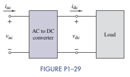
AC to DC Converter
A manufacturer's data sheet for the converter in Figure P1-29 states that the output voltage is
Want to see the full answer?
Check out a sample textbook solution
Chapter 1 Solutions
ANALYSIS+DESIGN OF LINEAR CIRCUITS(LL)


- Consider the circuit shown in Figure P1.61. Find the power for the voltage source and for the current source. Which source is absorbing power?arrow_forwardUse KVL to solve for the voltages v a, v b and v c in Figure P1.42arrow_forwardFor the (R-C) circuit shown in figure (1-5) , plot the output response y(t) for unit step input e(t) mathematicallyarrow_forward
- Illustrate the following equations using circuits of switches:(c.) X+X'ZY = X+YZ (d.) (A+B)C+(A+B)C=A+Barrow_forwardConsider the circuit shown in Figure P1.68. a. Which elements are in series?b. Which elements are in parallel? c. Apply Ohm’s and Kirchhoff’s laws to solve for R x.arrow_forwardYou are working as an electrician in a large steel manufacturing plant, and you are in the process of doing preventive maintenance on a large DC generator. You have megged both the series and shunt field windings and found that each has over 10 M to ground. Your ohmmeter, however, indicates a resistance of 1.5 across terminals S1andS2. The ohmmeter indicates a resistance of 225 between terminals F1andF2. Are these readings normal for this type machine, or is there a likely problem? Explain your answer.arrow_forward
- DEGREE: Electrical Engineering SUBJECT/COURSE: AC CircuitsTOPIC: Converter and Rectifier NOTE: Please solve in this way. 1. Please have a good handwriting, some of the answers are not readable. Thank you!2. GIVEN. (Include symbols and units)3. REQUIRED/FIND/MISSING (with symbol/s)4. ILLUSTRATION (Required).5. Step-by-step SOLUTION with Formulas and Symbols. No Shortcut, No skipping, and detailed as possible6. FINAL ANSWERS must be rounded up to three decimal places PROBLEM: A three-phase converter has a d-c rating of 120kw and 600volts. Assuming an efficiency of 94 percent and a power factor of 0.95, calculate:(A) the direct-current output(B) the slip-ring voltage and the slip-ring current(C) Also determine the kilovolt-ampere load on each of the transformers.arrow_forwardConsider the circuit in the given figure. Assume R1 = 140 Ω and R2 = 280 Ω. Calculate current i in the given figure when the switch is in position 2.arrow_forwardSolve parts a , b & carrow_forward
 Delmar's Standard Textbook Of ElectricityElectrical EngineeringISBN:9781337900348Author:Stephen L. HermanPublisher:Cengage Learning