Mechanics of Materials-Access (1 Sem. )
7th Edition
ISBN: 9780077625191
Author: BEER
Publisher: MCG
expand_more
expand_more
format_list_bulleted
Videos
Textbook Question
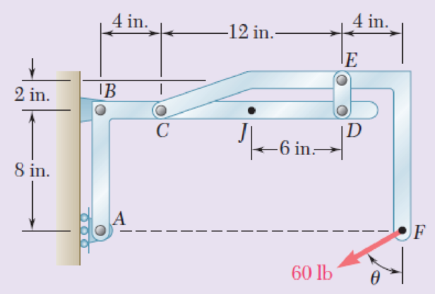
Chapter 1, Problem 64RP
Knowing that link DE is
Fig. P1.64
Expert Solution & Answer
Want to see the full answer?
Check out a sample textbook solution
Students have asked these similar questions
Two gage marks are placed exactly 250 mm apart on a 12-mm-diameter aluminum rod with E = 73 GPa and an ultimate strength of 140 MPa. Knowing that the distance between the gage marks is 250.28 mm after a load is applied, determine the stress in the rod
A 5-kN tensile load will be applied to a 50-m length of steel wire with E = 200 GPa. Determine the smallest diameter wire that can be used, knowing that the normal stress must not exceed 150 MPa and that the increase in length of the wire must not exceed 25 mm.
Knowing that, for the plate shown, the allowable stress is 125 MPa, determine the maximum allowable value of P when (a) r=12 mm, (b) r= 18 mm
Chapter 1 Solutions
Mechanics of Materials-Access (1 Sem. )
Ch. 1.2 - Two solid cylindrical rods AB and BC are welded...Ch. 1.2 - Two solid cylindrical rods AB and BC are welded...Ch. 1.2 - Two solid cylindrical rods AB and BC are welded...Ch. 1.2 - Two solid cylindrical rods AB and BC are welded...Ch. 1.2 - A strain gage located at C on the surface of bone...Ch. 1.2 - Two brass rods AB and BC, each of uniform...Ch. 1.2 - Each of the four vertical links has an 8 36-mm...Ch. 1.2 - Link AC has a uniform rectangular cross section 18...Ch. 1.2 - Three forces, each of magnitude P = 4 kN, are...Ch. 1.2 - Link BD consists of a single bar 1 in. wide and 12...
Ch. 1.2 - For the Pratt bridge truss and loading shown,...Ch. 1.2 - The frame shown consists of four wooden members,...Ch. 1.2 - An aircraft tow bar is positioned by means of a...Ch. 1.2 - Two hydraulic cylinders are used to control the...Ch. 1.2 - Determine the diameter of the largest circular...Ch. 1.2 - Two wooden planks, each 12 in. thick and 9 in....Ch. 1.2 - When the force P reached 1600 lb, the wooden...Ch. 1.2 - A load P is applied to a steel rod supported as...Ch. 1.2 - The axial force in the column supporting the...Ch. 1.2 - Three wooden planks are fastened together by a...Ch. 1.2 - A 40-kN axial load is applied to a short wooden...Ch. 1.2 - An axial load P is supported by a short W8 40...Ch. 1.2 - Link AB, of width b = 2 in. and thickness t=14...Ch. 1.2 - Determine the largest load P that can be applied...Ch. 1.2 - Knowing that = 40 and P = 9 kN, determine (a) the...Ch. 1.2 - The hydraulic cylinder CF, which partially...Ch. 1.2 - For the assembly and loading of Prob. 1.7,...Ch. 1.2 - Two identical linkage-and-hydraulic-cylinder...Ch. 1.5 - Two wooden members of uniform rectangular cross...Ch. 1.5 - Two wooden members of uniform rectangular cross...Ch. 1.5 - The 1.4-kip load P is supported by two wooden...Ch. 1.5 - Two wooden members of uniform cross section are...Ch. 1.5 - A centric load P is applied to the granite block...Ch. 1.5 - A 240-kip load P is applied to the granite block...Ch. 1.5 - A steel pipe of 400-mm outer diameter is...Ch. 1.5 - A steel pipe of 400-mm outer diameter is...Ch. 1.5 - A steel loop ABCD of length 5 ft and of 38-in....Ch. 1.5 - Link BC is 6 mm thick, has a width w = 25 mm, and...Ch. 1.5 - Link BC is 6 mm thick and is made of a steel with...Ch. 1.5 - Members AB and BC of the truss shown are made of...Ch. 1.5 - Members AB and BC of the truss shown are made of...Ch. 1.5 - Link AB is to be made of a steel for which the...Ch. 1.5 - Two wooden members are joined by plywood splice...Ch. 1.5 - For the joint and loading of Prob. 1.43, determine...Ch. 1.5 - Three 34-in.-diameter steel bolts are to be used...Ch. 1.5 - Three steel bolts are to be used to attach the...Ch. 1.5 - A load P is supported as shown by a steel pin that...Ch. 1.5 - A load P is supported as shown by a steel pin that...Ch. 1.5 - A steel plate 14 in. thick is embedded in a...Ch. 1.5 - Determine the factor of safety for the cable...Ch. 1.5 - Link AC is made of a steel with a 65-ksi ultimate...Ch. 1.5 - Solve Prob. 1.51, assuming that the structure has...Ch. 1.5 - Each of the two vertical links CF connecting the...Ch. 1.5 - Solve Prob. 1.53, assuming that the pins at C and...Ch. 1.5 - In the structure shown, an 8-mm-diameter pin is...Ch. 1.5 - In an alternative design for the structure of...Ch. 1.5 - Prob. 57PCh. 1.5 - The Load and Resistance Factor Design method is to...Ch. 1 - In the marine crane shown, link CD is known to...Ch. 1 - Two horizontal 5-kip forces are applied to pin B...Ch. 1 - For the assembly and loading of Prob. 1.60,...Ch. 1 - Two steel plates are to be held together by means...Ch. 1 - A couple M of magnitude 1500 N m is applied to...Ch. 1 - Knowing that link DE is 18 in. thick and 1 in....Ch. 1 - A 58-in.-diameter steel rod AB is fitted to a...Ch. 1 - In the steel structure shown, a 6-mm-diameter pin...Ch. 1 - Prob. 67RPCh. 1 - A force P is applied as shown to a steel...Ch. 1 - The two portions of member AB are glued together...Ch. 1 - The two portions of member AB are glued together...
Knowledge Booster


Learn more about
Need a deep-dive on the concept behind this application? Look no further. Learn more about this topic, mechanical-engineering and related others by exploring similar questions and additional content below.Similar questions
- Two gage marks are placed exactly 250 mm apart on a 12-mm-diameter aluminum rod with E5 73 GPa and an ultimate strength of 140 MPa. Knowing that the distance between the gage marks is 250.28 mm after a load is applied, determine (a) the stress in the rod, (b) the factor of safety.arrow_forwardThree wooden planks are fastened together by a series of bolts to form a column. The diameter of each bolt is 12 mm and the inner diameter of each washer is 16 mm, which is slightly larger than the diameter of the holes in the planks. Determine the smallest allowable outer diameter d of the washers, knowing that the average normal stress in the bolts is 36 MPa and that the bearing stress between the washers and the planks must not exceed 8.5 MPa.arrow_forwardA fabric used in air-inflated structures is subjected to a biaxial loading that results in normal stresses ox = 18 ksi and oz = 24 ksi.Knowing that the properties of the fabric can be approximated as E = 12.6 x 10 psi and v = 0.34, determine the change in length of (a) side AB, (b) side BC, (c) diagonal AC.arrow_forward
- Knowing that a 0.02-in. gap exists when the temperature is 75°F, determine (a) the temperature at which the normal stress in the alumi-num bar will be equal to –11 ksi, (b) the corresponding exact length of the aluminum bar.arrow_forwardKnowing that connecting rod BD has a uniform cross section of area equal to 800 mm², determine the magnitude of the load P so that the normal stress in rod BD is 50 MPa.arrow_forwardA 5.3-m-long steel rod must not stretch more than 2.71 mm and the normal stress must not exceed 181 MPa when the rod is subjected to a 9.99-kNaxial load. Knowing that E = 199.3 GPa, determine the required radius of the rod in mm. Express your answer in four decimal places.arrow_forward
- Two solid cylindrical rods AB and BC are welded together at B and loaded as shown. Knowing that the average normal stress must not exceed 175 MPa in rod AB and 150 MPa in rod BC, determine the smallest allowable values of d1 and d2.arrow_forwardEach of the four vertical Ilinks has an 8 x 36-mm uniform rectangular cross section and each of the four pins has a 16-mm diameter. Take P= 19 kN. 0.4 m C 0.25 m 0.2 m B. P Determine the average bearing stress at Bin member ABC, knowing that this member has a 10 x 50-mm uniform rectangular cross section. MPa. The average bearing stress at Bin member ABC is.arrow_forwardA14-kN tensile load will be applied to a 50-m length of steel wire with E = 200 GPa. Determine the smallest diameter wire that can be used, knowing that the normal stress must not exceed 150 MPa and that the increase in length of the wire must not exceed 25 mm. The smallest diameter that can be used is ___mm?arrow_forward
- Two gage marks are placed exactly 250mm apart on a 12mm-diameter aluminum rod with E=73Gpa and an ultimate strength of 140Mpa. Knowing that the distance between the gage marks is 250.28mm after a load is applied, determine (a) the stress in the rod, (b) the factor of safety.arrow_forwardTwo steel plates are to be held together by means of 16-mm-diameter high-strength steel bolts fitting snugly inside cylindrical brass spacers. Knowing that the average normal stress must not exceed 205 MPa in the bolts and 132 MPa in the spacers, determine the outer diameter of the spacers that yields the most economical and safe design. The outer diameter of the spacers that yields the most economical and safe design is mm.arrow_forwardA steel plate 5/16 in. thick is embedded in a horizontal concrete slab and is used to anchor a high-strength vertical cable as shown. The diameter of the hole in the plate is 3/4in., the ultimate strength of the steel used is 36 ksi, and the ultimate bonding stress between plate and concrete is 300 psi. Knowing that a factor of safety of 3.60 is desired when P = 2.5 kips, determine (a) the required width a of the plate,(b) the minimum depth b to which a plate of that width should be embedded in the concrete slab. (Neglect the normal stresses betweenthe concrete and the lower end of the plate.)arrow_forward
arrow_back_ios
SEE MORE QUESTIONS
arrow_forward_ios
Recommended textbooks for you
 Elements Of ElectromagneticsMechanical EngineeringISBN:9780190698614Author:Sadiku, Matthew N. O.Publisher:Oxford University Press
 Mechanics of Materials (10th Edition)Mechanical EngineeringISBN:9780134319650Author:Russell C. HibbelerPublisher:PEARSON
 Thermodynamics: An Engineering ApproachMechanical EngineeringISBN:9781259822674Author:Yunus A. Cengel Dr., Michael A. BolesPublisher:McGraw-Hill Education
 Control Systems EngineeringMechanical EngineeringISBN:9781118170519Author:Norman S. NisePublisher:WILEY
 Mechanics of Materials (MindTap Course List)Mechanical EngineeringISBN:9781337093347Author:Barry J. Goodno, James M. GerePublisher:Cengage Learning
 Engineering Mechanics: StaticsMechanical EngineeringISBN:9781118807330Author:James L. Meriam, L. G. Kraige, J. N. BoltonPublisher:WILEY
Elements Of Electromagnetics
Mechanical Engineering
ISBN:9780190698614
Author:Sadiku, Matthew N. O.
Publisher:Oxford University Press
Mechanics of Materials (10th Edition)
Mechanical Engineering
ISBN:9780134319650
Author:Russell C. Hibbeler
Publisher:PEARSON
Thermodynamics: An Engineering Approach
Mechanical Engineering
ISBN:9781259822674
Author:Yunus A. Cengel Dr., Michael A. Boles
Publisher:McGraw-Hill Education
Control Systems Engineering
Mechanical Engineering
ISBN:9781118170519
Author:Norman S. Nise
Publisher:WILEY
Mechanics of Materials (MindTap Course List)
Mechanical Engineering
ISBN:9781337093347
Author:Barry J. Goodno, James M. Gere
Publisher:Cengage Learning
Engineering Mechanics: Statics
Mechanical Engineering
ISBN:9781118807330
Author:James L. Meriam, L. G. Kraige, J. N. Bolton
Publisher:WILEY
An Introduction to Stress and Strain; Author: The Efficient Engineer;https://www.youtube.com/watch?v=aQf6Q8t1FQE;License: Standard YouTube License, CC-BY