
MECHANICS OF MATERIALS (LL) & ACCESS CA
7th Edition
ISBN: 9781260435306
Author: BEER
Publisher: MCG
expand_more
expand_more
format_list_bulleted
Videos
Textbook Question
Chapter 1, Problem 69RP
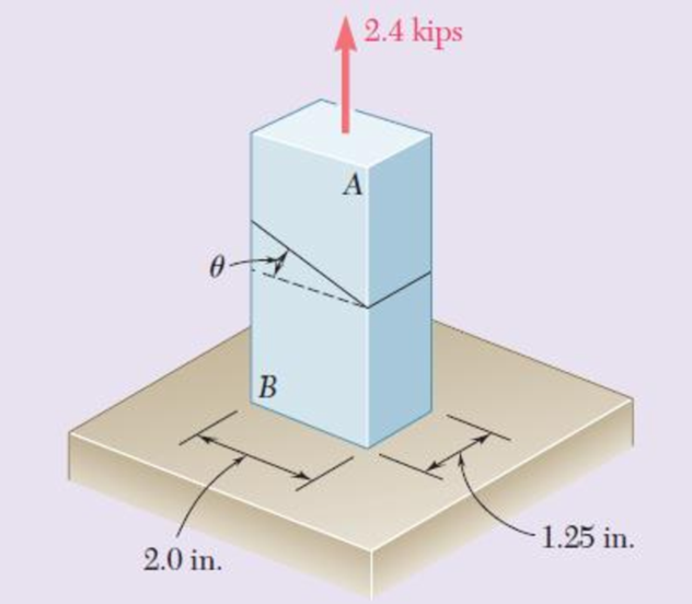
The two portions of member AB are glued together along a plane forming an angle θ with the horizontal. Knowing that the ultimate stress for the glued joint is 2.5 ksi in tension and 1.3 ksi in shear, determine (a) the value of θ for which the factor of safety of the member is maximum, (b) the corresponding value of the factor of safety. (Hint: Equate the expressions obtained for the factors of safety with respect to the normal and shearing stresses.)
Fig. P1.69 and P1.70
Expert Solution & Answer
Want to see the full answer?
Check out a sample textbook solution
Students have asked these similar questions
Knowing that connecting rod BD has a uniform cross section of area equal to 800 mm², determine the magnitude of the load P so that the normal stress in rod BD is 50 MPa.
In the structure shown, an 8-mm-diameter pin is used at A, and 12-mm-diameter pins are used at B and D. Knowing that the ultimate shearing stress is 100 MPa at all connections and that the ultimate normal stress is 250 MPa in each of the two links joining B and D, determine the allowable load P if an overall factor of safety of 2.6 is desired.
The change in diameter of a large steel bolt is carefully measured as the nut is tightened. Knowing that E= 29 *106 psi and ν= 0.30, determine the internal force in the bolt if the diameter is observed to decrease by 0.5 *103 in
Chapter 1 Solutions
MECHANICS OF MATERIALS (LL) & ACCESS CA
Ch. 1.2 - Two solid cylindrical rods AB and BC are welded...Ch. 1.2 - Two solid cylindrical rods AB and BC are welded...Ch. 1.2 - Two solid cylindrical rods AB and BC are welded...Ch. 1.2 - Two solid cylindrical rods AB and BC are welded...Ch. 1.2 - A strain gage located at C on the surface of bone...Ch. 1.2 - Two brass rods AB and BC, each of uniform...Ch. 1.2 - Each of the four vertical links has an 8 36-mm...Ch. 1.2 - Link AC has a uniform rectangular cross section 18...Ch. 1.2 - Three forces, each of magnitude P = 4 kN, are...Ch. 1.2 - Link BD consists of a single bar 1 in. wide and 12...
Ch. 1.2 - For the Pratt bridge truss and loading shown,...Ch. 1.2 - The frame shown consists of four wooden members,...Ch. 1.2 - An aircraft tow bar is positioned by means of a...Ch. 1.2 - Two hydraulic cylinders are used to control the...Ch. 1.2 - Determine the diameter of the largest circular...Ch. 1.2 - Two wooden planks, each 12 in. thick and 9 in....Ch. 1.2 - When the force P reached 1600 lb, the wooden...Ch. 1.2 - A load P is applied to a steel rod supported as...Ch. 1.2 - The axial force in the column supporting the...Ch. 1.2 - Three wooden planks are fastened together by a...Ch. 1.2 - A 40-kN axial load is applied to a short wooden...Ch. 1.2 - An axial load P is supported by a short W8 40...Ch. 1.2 - Link AB, of width b = 2 in. and thickness t=14...Ch. 1.2 - Determine the largest load P that can be applied...Ch. 1.2 - Knowing that = 40 and P = 9 kN, determine (a) the...Ch. 1.2 - The hydraulic cylinder CF, which partially...Ch. 1.2 - For the assembly and loading of Prob. 1.7,...Ch. 1.2 - Two identical linkage-and-hydraulic-cylinder...Ch. 1.5 - Two wooden members of uniform rectangular cross...Ch. 1.5 - Two wooden members of uniform rectangular cross...Ch. 1.5 - The 1.4-kip load P is supported by two wooden...Ch. 1.5 - Two wooden members of uniform cross section are...Ch. 1.5 - A centric load P is applied to the granite block...Ch. 1.5 - A 240-kip load P is applied to the granite block...Ch. 1.5 - A steel pipe of 400-mm outer diameter is...Ch. 1.5 - A steel pipe of 400-mm outer diameter is...Ch. 1.5 - A steel loop ABCD of length 5 ft and of 38-in....Ch. 1.5 - Link BC is 6 mm thick, has a width w = 25 mm, and...Ch. 1.5 - Link BC is 6 mm thick and is made of a steel with...Ch. 1.5 - Members AB and BC of the truss shown are made of...Ch. 1.5 - Members AB and BC of the truss shown are made of...Ch. 1.5 - Link AB is to be made of a steel for which the...Ch. 1.5 - Two wooden members are joined by plywood splice...Ch. 1.5 - For the joint and loading of Prob. 1.43, determine...Ch. 1.5 - Three 34-in.-diameter steel bolts are to be used...Ch. 1.5 - Three steel bolts are to be used to attach the...Ch. 1.5 - A load P is supported as shown by a steel pin that...Ch. 1.5 - A load P is supported as shown by a steel pin that...Ch. 1.5 - A steel plate 14 in. thick is embedded in a...Ch. 1.5 - Determine the factor of safety for the cable...Ch. 1.5 - Link AC is made of a steel with a 65-ksi ultimate...Ch. 1.5 - Solve Prob. 1.51, assuming that the structure has...Ch. 1.5 - Each of the two vertical links CF connecting the...Ch. 1.5 - Solve Prob. 1.53, assuming that the pins at C and...Ch. 1.5 - In the structure shown, an 8-mm-diameter pin is...Ch. 1.5 - In an alternative design for the structure of...Ch. 1.5 - Prob. 57PCh. 1.5 - The Load and Resistance Factor Design method is to...Ch. 1 - In the marine crane shown, link CD is known to...Ch. 1 - Two horizontal 5-kip forces are applied to pin B...Ch. 1 - For the assembly and loading of Prob. 1.60,...Ch. 1 - Two steel plates are to be held together by means...Ch. 1 - A couple M of magnitude 1500 N m is applied to...Ch. 1 - Knowing that link DE is 18 in. thick and 1 in....Ch. 1 - A 58-in.-diameter steel rod AB is fitted to a...Ch. 1 - In the steel structure shown, a 6-mm-diameter pin...Ch. 1 - Prob. 67RPCh. 1 - A force P is applied as shown to a steel...Ch. 1 - The two portions of member AB are glued together...Ch. 1 - The two portions of member AB are glued together...
Knowledge Booster


Learn more about
Need a deep-dive on the concept behind this application? Look no further. Learn more about this topic, mechanical-engineering and related others by exploring similar questions and additional content below.Similar questions
- Knowing that the hole has a diameter of 9 mm, determine (a) the radius rf of the fillets for which the same maximum stress occursat the hole A and at the fillets, (b) the corresponding maximum allowable load P if the allowable stress is 100 MPa.arrow_forwardA load P is supported as shown by a steel pin that has been inserted in a short wooden member hanging from the ceiling. The ultimate strength of the wood used is 60 MPa in tension and 7.5 MPa in shear,while the ultimate strength of the steel is 145 MPa in shear. Knowing that b = 40 mm, c = 55 mm, and d = 12 mm, determine the load P if an overall factor of safety of 3.2 is desired.arrow_forwardA rod must not stretch more than 6 mm when the tension in the wire is 8 kN. Knowing that E = 105 GPa and that the maximum allowable normal stress is 150 MPa, determine the smallest diameter (mm) rod that should be used.arrow_forward
- Two wooden members of uniform rectangular cross section of sides a = 100 mm and b = 60 mm are joined by a simple glued joint as shown. Knowing that the ultimate stresses for the joint are σU =1.26 MPa in tension and τU = 1.50 MPa in shear and that P =6 kN, determine the factor of safety for the joint when (a) α =20°,(b) α =35°, (c) α =45°. For each of these values of α, also determine whether the joint will fail in tension or in shear if P is increased until rupture occurs.arrow_forwardA rod must not stretch more than 6 mm when the tension in the wire is 8 kN. Knowing that E = 105 GPa and that the maximum allowable normal stress is 150 MPa, determine the corresponding maximum length of the rod (m).arrow_forwardEach of the four vertical Ilinks has an 8 x 36-mm uniform rectangular cross section and each of the four pins has a 16-mm diameter. Take P= 19 kN. 0.4 m C 0.25 m 0.2 m B. P Determine the average bearing stress at Bin member ABC, knowing that this member has a 10 x 50-mm uniform rectangular cross section. MPa. The average bearing stress at Bin member ABC is.arrow_forward
- Knowing that the couple shown acts in a vertical plane, determine the stress at (a) point A, (b) point B.arrow_forwardKnowing that the hole has a diameter of 9 mm, determine (a) the radius rf of the fillets for which the same maximum stress occurs at the hole A and at the fillets, (b) the corresponding maximum allowable load Pif the allowable stress is 100 MPaarrow_forwardThe ABC element is supported by a pin at C and a BD cable. Knowing that the limit load for the BD cable is 150 kN, and the coefficient Safety with respect to cable failure for BD of 3.5 determine the maximum value of the load P that can be supported. Determine the diameter of pin C, knowing that it is made of steel with an admissible stress of σadm = 270 Mpa, and that it is subjected to shear double.arrow_forward
- Two loads are applied to the bracket BCD as shown. (a) Knowing that the control rod AB is to be made of a steel having an ultimate normal stress of 600 MPa, determine the diameter of the rod for which the factor of safetywith respect to failure will be 3.3. (b) The pin at C is to be made of a steelhaving an ultimate shearing stress of 350 MPa. Determine the diameter ofthe pin C for which the factor of safety with respect to shear will also be 3.3.(c) Determine the required thickness of the bracket supports at C, knowingthat the allowable bearing stress of the steel used is 300 MPa.arrow_forwardKnowing that a force of 800N is applied to the indicated pedal, determine the diameter of the pin at C such that the average shear stress in the pin is 35 MPa.arrow_forwardKnowing that, for the plate shown, the allowable stress is 125 MPa, determine the maximum allowable value of P when (a) r=12 mm, (b) r= 18 mmarrow_forward
arrow_back_ios
SEE MORE QUESTIONS
arrow_forward_ios
Recommended textbooks for you
 Elements Of ElectromagneticsMechanical EngineeringISBN:9780190698614Author:Sadiku, Matthew N. O.Publisher:Oxford University Press
 Mechanics of Materials (10th Edition)Mechanical EngineeringISBN:9780134319650Author:Russell C. HibbelerPublisher:PEARSON
 Thermodynamics: An Engineering ApproachMechanical EngineeringISBN:9781259822674Author:Yunus A. Cengel Dr., Michael A. BolesPublisher:McGraw-Hill Education
 Control Systems EngineeringMechanical EngineeringISBN:9781118170519Author:Norman S. NisePublisher:WILEY
 Mechanics of Materials (MindTap Course List)Mechanical EngineeringISBN:9781337093347Author:Barry J. Goodno, James M. GerePublisher:Cengage Learning
 Engineering Mechanics: StaticsMechanical EngineeringISBN:9781118807330Author:James L. Meriam, L. G. Kraige, J. N. BoltonPublisher:WILEY
Elements Of Electromagnetics
Mechanical Engineering
ISBN:9780190698614
Author:Sadiku, Matthew N. O.
Publisher:Oxford University Press
Mechanics of Materials (10th Edition)
Mechanical Engineering
ISBN:9780134319650
Author:Russell C. Hibbeler
Publisher:PEARSON
Thermodynamics: An Engineering Approach
Mechanical Engineering
ISBN:9781259822674
Author:Yunus A. Cengel Dr., Michael A. Boles
Publisher:McGraw-Hill Education
Control Systems Engineering
Mechanical Engineering
ISBN:9781118170519
Author:Norman S. Nise
Publisher:WILEY
Mechanics of Materials (MindTap Course List)
Mechanical Engineering
ISBN:9781337093347
Author:Barry J. Goodno, James M. Gere
Publisher:Cengage Learning
Engineering Mechanics: Statics
Mechanical Engineering
ISBN:9781118807330
Author:James L. Meriam, L. G. Kraige, J. N. Bolton
Publisher:WILEY
An Introduction to Stress and Strain; Author: The Efficient Engineer;https://www.youtube.com/watch?v=aQf6Q8t1FQE;License: Standard YouTube License, CC-BY