![MindTap Engineering for Das/Sobhan's Principles of Geotechnical Engineering, 9th Edition, [Instant Access], 2 terms (12 months)](https://s3.amazonaws.com/compass-isbn-assets/textbook_empty_images/large_textbook_empty.svg)
MindTap Engineering for Das/Sobhan's Principles of Geotechnical Engineering, 9th Edition, [Instant Access], 2 terms (12 months)
9th Edition
ISBN: 9781305971257
Author: Braja M. Das; Khaled Sobhan
Publisher: Cengage Learning US
expand_more
expand_more
format_list_bulleted
Concept explainers
Videos
Textbook Question
Chapter 10, Problem 10.13P
Repeat Problem 10.12 for q = 700 kN/m2, B = 8 m, and z = 4 m. In this case, point A is located below the centerline under the strip load.
10.12 Refer to Figure 10.43. A strip load of q = 1450 lb/ft2 is applied over a width with B = 48 ft. Determine the increase in vertical stress at point A located z = 21 ft below the surface. Given x = 28.8 ft.
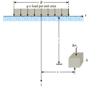
Figure 10.43
Expert Solution & Answer

Trending nowThis is a popular solution!

Students have asked these similar questions
Refer to Figure 10.40. Determine the vertical stress
increase, Aoz, at point A with the following values: q1 =
90 kN/m; q2 = 325 kN/m; x1 = 4 m; x2 = 2.5 m; z = 3 m
Line kad -
Line load -
4- A strip load of q= 100 lb/ft is applied over a width, B=10 ft. Determine the increase in vertical stress at point A
located z =4.6 ft below the surface. Given: x-8.2 ft.
q = load per unit arca
The rectangular bar shown in the figure is subjected to a uniformly distributed axial loading of w = 11 kN/m and a concentrated force of P = 14 kN at B. Determine the magnitude of the maximum normal stress in the bar and its location x. Assume a = 0.9 m, b = 1.1 m, c = 20 mm, and d = 35 mm.
Chapter 10 Solutions
MindTap Engineering for Das/Sobhan's Principles of Geotechnical Engineering, 9th Edition, [Instant Access], 2 terms (12 months)
Ch. 10 - Prob. 10.1PCh. 10 - Prob. 10.2PCh. 10 - Prob. 10.3PCh. 10 - Prob. 10.4PCh. 10 - Prob. 10.5PCh. 10 - Prob. 10.6PCh. 10 - Point loads of magnitude 125, 250, and 500 kN act...Ch. 10 - Refer to Figure 10.41. Determine the vertical...Ch. 10 - For the same line loads given in Problem 10.8,...Ch. 10 - Refer to Figure 10.41. Given: q2 = 3800 lb/ft, x1...
Ch. 10 - Refer to Figure 10.42. Due to application of line...Ch. 10 - Refer to Figure 10.43. A strip load of q = 1450...Ch. 10 - Repeat Problem 10.12 for q = 700 kN/m2, B = 8 m,...Ch. 10 - Prob. 10.14PCh. 10 - For the embankment shown in Figure 10.45,...Ch. 10 - Refer to Figure 10.46. A flexible circular area of...Ch. 10 - Refer to Figure 10.47. A flexible rectangular area...Ch. 10 - Refer to the flexible loaded rectangular area...Ch. 10 - Prob. 10.19PCh. 10 - Prob. 10.20PCh. 10 - Refer to Figure 10.48. If R = 4 m and hw = height...Ch. 10 - Refer to Figure 10.49. For the linearly increasing...Ch. 10 - EB and FG are two planes inside a soil element...Ch. 10 - A soil element beneath a pave ment experiences...
Knowledge Booster


Learn more about
Need a deep-dive on the concept behind this application? Look no further. Learn more about this topic, civil-engineering and related others by exploring similar questions and additional content below.Similar questions
- Problem 2 Two 10-kN forces are applied to a 20 x 60-mm rectangular bar as shown. Determine the stress at point A when (a) b = 0, (b) b = 10 mm, (c) b = 25 mm. 10 mm 10 mm 30 mm 10 kN 30 mm 10 kN 25 mmarrow_forward10.12 Refer to Figure 10.42. A strip load of q = 43 kN/m? is applied over a width, B= 11 m. Determine the increase in vertical stress at point A located z = 4.6 m below the surface. Given: x 8.2 m. q= load per unit areaarrow_forwardRefer to Figure P6.4. A strip load of q = 900 lb/ft2 is applied over a width B = 36 ft. Determine the increase in vertical stress at point A located z = 15 ft below the surface. Given: x = 27 ft.arrow_forward
- Referring to Figure Q2 (a), the vertical stress increase at point A is 25 kN/m2due to application of line loads q1 and q2. Determine the magnitude of q2.arrow_forwardRefer to figure below. The magnitude of the load is 120 kPa. Calculate the vertical stress at points, A , B, and C. 3 т 2 m |120 kPa B. 2 marrow_forwardA strip load of q = 100 kN/m2 is applied over a width, B = 10 m. Determine the increase in vertical stress at point A located z = 5 m below the surface. Given: x = 5 m. Please have the answer in four (4) decimal places. = load per unit area Figure 3.15arrow_forward
- 4. A beam of rectangular cross section 40 mm by 100 mm is carrying a bending moment of M = 21 kN.m about its strong axis. Determine the residual stresses following removal of the bending moment (show the residual stress distribution). Consider oy = 240 MPa, and E = 200 GPa. Solution: 100 mm 40 mmarrow_forwardProb. 3 The plan of a flexible rectangular loaded area is shown in Figure below. The uniformly distributed load on the flexible area, q, is 100 kN/m². Determine the increase in the vertical stress, Aoz, at a depth of z = 2 m below a. Point A b. Point B c. Point C 4 m 1.6 m 2 m 0.8 m q = 100 kN/m² A 1.2 m-arrow_forwardI want Normal stress developed in segment AB. A homogeneous bar with a cross-sectional area of 400 mm2 is attached to fixed supports as shown inthe figure. It is subjected to lateral forces P1 = 20 kN and P2 = 50 kN. Determine the normal stressdeveloped in segments AB and BC. Answer: σAB = 80.55 MPaarrow_forward
- A rectangular distributed load of 100 kPa is applied to the soil surface. An additional circular distributed load of 200 kPa is applied on one side of the previous load. Determine the vertical effective stress 6 m below point A due to the application of both loads. R= 6 m 6 m 6 m 6 m 200 kPa 6 m 6 m 100 kPa 6 marrow_forwardQuestion 03: Determine the normal stress and draw the stress diagram of the beam at a point 1 m from the left support. 1.0m 20KN/M D ↓ ↓ ↓ ↓ J J 2.0m 1=225x106mm² Bean depth = z 300mmarrow_forwardProblem 6. [Concepts: Spatially varying average normal stress, and integration] The bar has a cross-sectional area of 400(106) m². If it is subjected to a triangular axial distributed loading along its length which is 0 at x = 0 and 9 kN/m at x = 1.5 m, and to two concentrated loads as shown in the figure. a) Determine the average normal stress in the bar as a function of x for 0arrow_forwardarrow_back_iosSEE MORE QUESTIONSarrow_forward_ios
Recommended textbooks for you
 Principles of Geotechnical Engineering (MindTap C...Civil EngineeringISBN:9781305970939Author:Braja M. Das, Khaled SobhanPublisher:Cengage Learning
 Principles of Foundation Engineering (MindTap Cou...Civil EngineeringISBN:9781305081550Author:Braja M. DasPublisher:Cengage Learning
Principles of Geotechnical Engineering (MindTap C...
Civil Engineering
ISBN:9781305970939
Author:Braja M. Das, Khaled Sobhan
Publisher:Cengage Learning
Principles of Foundation Engineering (MindTap Cou...
Civil Engineering
ISBN:9781305081550
Author:Braja M. Das
Publisher:Cengage Learning
Stress Distribution in Soils GATE 2019 Civil | Boussinesq, Westergaard Theory; Author: Gradeup- GATE, ESE, PSUs Exam Preparation;https://www.youtube.com/watch?v=6e7yIx2VxI0;License: Standard YouTube License, CC-BY