![MindTap Engineering for Das/Sobhan's Principles of Geotechnical Engineering, 9th Edition, [Instant Access], 2 terms (12 months)](https://s3.amazonaws.com/compass-isbn-assets/textbook_empty_images/large_textbook_empty.svg)
MindTap Engineering for Das/Sobhan's Principles of Geotechnical Engineering, 9th Edition, [Instant Access], 2 terms (12 months)
9th Edition
ISBN: 9781305971257
Author: Braja M. Das; Khaled Sobhan
Publisher: Cengage Learning US
expand_more
expand_more
format_list_bulleted
Concept explainers
Videos
Textbook Question
Chapter 10, Problem 10.21P
Refer to Figure 10.48. If R = 4 m and hw = height of water = 5 m, determine the vertical stress increases 2 m below the loaded area at radial distances where r = 0, 2, 4, 6, and 8 m.
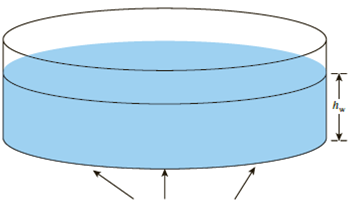
Circular contact area of radius R on the ground surface
Figure 10.48
Expert Solution & Answer
Want to see the full answer?
Check out a sample textbook solution
Students have asked these similar questions
3- Due to application of line loads q1 and q2, the vertical stress increase at point A is 42 lb/ft?. Determine the
magnitude of q2
q.=292 Ib/ft
92
45°
4.5 ft
3 ft
3 ft
A
1. Three point loads, 19000, 20000 and 18000kN, act in line 8 m, 6m apart near the surface
of a soil mass. Calculate the vertical stress at a depth of 4m vertically below the center (30000kN)
load.
19 000 KN
20 000 kN
18 000 KN
Influence factors for vertical stress due to point load
↳
riz
b
riz
1₂
0.478
0.80
0.139
0.020
0.466
0.90
0.108
0.016
0.433
1.00
0.084
0.013
4 m
0.385
1.10
0.066
0.011
0.329
1.20
0.051
0.009
0.273
1.30
0.040
0.006
0.221
1.40
0.032
0.004
0.176
1.50
0.025
0.003
8 m
6m
riz
0.00
0.10
0.20
0.30
0.40
0.50
0.60
0.70
1.60
1.70
1.80
1.90
2.00
2.20
2.40
2.60
a= 3
b= 0
c= 4
d= 7
Chapter 10 Solutions
MindTap Engineering for Das/Sobhan's Principles of Geotechnical Engineering, 9th Edition, [Instant Access], 2 terms (12 months)
Ch. 10 - Prob. 10.1PCh. 10 - Prob. 10.2PCh. 10 - Prob. 10.3PCh. 10 - Prob. 10.4PCh. 10 - Prob. 10.5PCh. 10 - Prob. 10.6PCh. 10 - Point loads of magnitude 125, 250, and 500 kN act...Ch. 10 - Refer to Figure 10.41. Determine the vertical...Ch. 10 - For the same line loads given in Problem 10.8,...Ch. 10 - Refer to Figure 10.41. Given: q2 = 3800 lb/ft, x1...
Ch. 10 - Refer to Figure 10.42. Due to application of line...Ch. 10 - Refer to Figure 10.43. A strip load of q = 1450...Ch. 10 - Repeat Problem 10.12 for q = 700 kN/m2, B = 8 m,...Ch. 10 - Prob. 10.14PCh. 10 - For the embankment shown in Figure 10.45,...Ch. 10 - Refer to Figure 10.46. A flexible circular area of...Ch. 10 - Refer to Figure 10.47. A flexible rectangular area...Ch. 10 - Refer to the flexible loaded rectangular area...Ch. 10 - Prob. 10.19PCh. 10 - Prob. 10.20PCh. 10 - Refer to Figure 10.48. If R = 4 m and hw = height...Ch. 10 - Refer to Figure 10.49. For the linearly increasing...Ch. 10 - EB and FG are two planes inside a soil element...Ch. 10 - A soil element beneath a pave ment experiences...
Knowledge Booster


Learn more about
Need a deep-dive on the concept behind this application? Look no further. Learn more about this topic, civil-engineering and related others by exploring similar questions and additional content below.Similar questions
- A rectangular concrete slab, 4.a m. x 5.d m. is shown in Figure 3.5, rests on the surface of a soil mass. The load acting on the center of the slah is 1785KN. Determine: 'The soil stress just below the slab. ;) The vertical stress increase at point A. a. b. Plan A 4.5 m Cross Section 3.8 m A 3.1 m Figure 3.5 5.3 marrow_forwardEx3: 50, 100, and 150 kN point loads are applied at Points A, B, and C, respectively, on the ground surface as seen in the figure. Compute the vertical stress increment under Point D down to the depth z = 20 m. 7.5 m 150 kN 50 kN 2m 5 m (Plane view) 100 kN 3 marrow_forwardStresses in soilarrow_forward
- a=1 b=7 c=4 d=4arrow_forwardRepeat Problem 10.12 for q = 700 kN/m2, B = 8 m, and z = 4 m. In this case, point A is located below the centerline under the strip load. 10.12 Refer to Figure 10.43. A strip load of q = 1450 lb/ft2 is applied over a width with B = 48 ft. Determine the increase in vertical stress at point A located z = 21 ft below the surface. Given x = 28.8 ft. Figure 10.43arrow_forwardRefer to Figure 10.43. A strip load of q = 1450 lb/ft2 is applied over a width with B = 48 ft. Determine the increase in vertical stress at point A located z = 21 ft below the surface. Given x = 28.8 ft. Figure 10.43arrow_forward
- The rectangular bar shown in the figure is subjected to a uniformly distributed axial loading of w = 11 kN/m and a concentrated force of P = 14 kN at B. Determine the magnitude of the maximum normal stress in the bar and its location x. Assume a = 0.9 m, b = 1.1 m, c = 20 mm, and d = 35 mm.arrow_forwardDetermine the average normal stress developed on the cross section as shown inFigure 1.arrow_forwardSoil mechanicsarrow_forward
- Marrow_forwardRefer to Figure P6.4. A strip load of q = 900 lb/ft2 is applied over a width B = 36 ft. Determine the increase in vertical stress at point A located z = 15 ft below the surface. Given: x = 27 ft.arrow_forwardb = 3 ft., L=5 ft., T=500 ft-lb CCW, P = 500 lb Dia. = 10 in., Area = 78.54 in^2, Ix=ly=D491 in^4, J = 982 in^4 1. Find APPLIED V, N, Mx, My, Mz at section where A is located looking in from y- axis 2. Calculate the normal stress at point A 3. Calculate the shear stress at point Aarrow_forward
arrow_back_ios
SEE MORE QUESTIONS
arrow_forward_ios
Recommended textbooks for you
 Principles of Geotechnical Engineering (MindTap C...Civil EngineeringISBN:9781305970939Author:Braja M. Das, Khaled SobhanPublisher:Cengage Learning
 Principles of Foundation Engineering (MindTap Cou...Civil EngineeringISBN:9781305081550Author:Braja M. DasPublisher:Cengage Learning
Principles of Geotechnical Engineering (MindTap C...
Civil Engineering
ISBN:9781305970939
Author:Braja M. Das, Khaled Sobhan
Publisher:Cengage Learning
Principles of Foundation Engineering (MindTap Cou...
Civil Engineering
ISBN:9781305081550
Author:Braja M. Das
Publisher:Cengage Learning
Stress Distribution in Soils GATE 2019 Civil | Boussinesq, Westergaard Theory; Author: Gradeup- GATE, ESE, PSUs Exam Preparation;https://www.youtube.com/watch?v=6e7yIx2VxI0;License: Standard YouTube License, CC-BY