
PRIN.OF GEOTECHNICAL...-MINDTAP(2 SEM)
9th Edition
ISBN: 9781305971271
Author: Das
Publisher: CENGAGE L
expand_more
expand_more
format_list_bulleted
Concept explainers
Videos
Textbook Question
Chapter 10, Problem 10.9P
For the same line loads given in Problem 10.8, determine the vertical stress increase, Δσz, at a point located 4 m below the line load, q2.
Refer to Figure 10.41. Determine the vertical stress increase, Δσz, at point A with the following values: q1 = 110 kN/m, q2 = 440 kN/m, x1 = 6 m, x2 = 3 m, and z = 4 m.
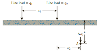
Figure 10.41
Expert Solution & Answer
Want to see the full answer?
Check out a sample textbook solution
Students have asked these similar questions
Refer to the figure below.
Given:
q1 = 100kN/m, q2 = 200 kN/m
X1 = 3m, x2 = 3m, z = 3m
Determine the vertical stress increase at point A. (11.46)
Line load = 4,
Line load = q,
x1
A
Based on the figure given below, determine the stress increase at Points A, B and C at a depth of 2 m below the ground surface.
←3 m
5 m
A
9₁ = 90 kPa
B
C
Problem 6:
From the figure below, given are the following;
q1 = 750 Ib/ft, xı = 8 ft, x2 = 4 ft, and z = 3 ft
If the vertical stress increase at point A due to the
loading is 35 Ib/ft?, determine the magnitude of q2.
%3D
Chapter 10 Solutions
PRIN.OF GEOTECHNICAL...-MINDTAP(2 SEM)
Ch. 10 - Prob. 10.1PCh. 10 - Prob. 10.2PCh. 10 - Prob. 10.3PCh. 10 - Prob. 10.4PCh. 10 - Prob. 10.5PCh. 10 - Prob. 10.6PCh. 10 - Point loads of magnitude 125, 250, and 500 kN act...Ch. 10 - Refer to Figure 10.41. Determine the vertical...Ch. 10 - For the same line loads given in Problem 10.8,...Ch. 10 - Refer to Figure 10.41. Given: q2 = 3800 lb/ft, x1...
Ch. 10 - Refer to Figure 10.42. Due to application of line...Ch. 10 - Refer to Figure 10.43. A strip load of q = 1450...Ch. 10 - Repeat Problem 10.12 for q = 700 kN/m2, B = 8 m,...Ch. 10 - Prob. 10.14PCh. 10 - For the embankment shown in Figure 10.45,...Ch. 10 - Refer to Figure 10.46. A flexible circular area of...Ch. 10 - Refer to Figure 10.47. A flexible rectangular area...Ch. 10 - Refer to the flexible loaded rectangular area...Ch. 10 - Prob. 10.19PCh. 10 - Prob. 10.20PCh. 10 - Refer to Figure 10.48. If R = 4 m and hw = height...Ch. 10 - Refer to Figure 10.49. For the linearly increasing...Ch. 10 - EB and FG are two planes inside a soil element...Ch. 10 - A soil element beneath a pave ment experiences...
Knowledge Booster


Learn more about
Need a deep-dive on the concept behind this application? Look no further. Learn more about this topic, civil-engineering and related others by exploring similar questions and additional content below.Similar questions
- Repeat Problem 10.12 for q = 700 kN/m2, B = 8 m, and z = 4 m. In this case, point A is located below the centerline under the strip load. 10.12 Refer to Figure 10.43. A strip load of q = 1450 lb/ft2 is applied over a width with B = 48 ft. Determine the increase in vertical stress at point A located z = 21 ft below the surface. Given x = 28.8 ft. Figure 10.43arrow_forwardRefer to Figure 8.24. Determine the vertical stress increase, , at point A with the following values: q1 = 100 kN/m x1 = 3 m z = 2 m q2 = 200 kN/m x2 = 2 m FIG. 8.24 Stress at a point due to two line loadsarrow_forwardRefer to Figure 10.46. A flexible circular area of radius 6 m is uniformly loaded. Given: q = 565 kN/m2. Using Newmarks chart, determine the increase in vertical stress, z, at point A. Figure 10.46arrow_forward
- Refer to Figure 10.40. Determine the vertical stress increase, Aoz, at point A with the following values: q1 = 90 kN/m; q2 = 325 kN/m; x1 = 4 m; x2 = 2.5 m; z = 3 m Line kad - Line load -arrow_forwardTake o, = 580 kPa (Figure 1) Express your answer to three significant figures and include the appropriate units. HÀ ? o, = Value Units Submit Request Answer Figure Part B Determine the shear stress acting on the inclined plane AB. Express your answer to three significant figures and include the appropriate units. В HA ? 30° Value Units Aarrow_forwardA strip load of q = 100 kN/m2 is applied over a width, B = 10 m. Determine the increase in vertical stress at point A located z = 5 m below the surface. Given: x = 5 m. Please have the answer in four (4) decimal places. = load per unit area Figure 3.15arrow_forward
- N B 0 Horizontal The stresses shown in the figure are applied at a point in a dry clayey sand soil mass. A= 50 kPa and B= 125 kPa The shear strength parameters of the clayey sand are: c'= 9kPa and p'=29° 0=30° a) The value of the shear stress, T, is slowly increased. What value would cause shear failure at this point (in kPa)? b) At failure, what angle does the failure plane make with the horizontal (in degrees)?arrow_forwardUse Eq. (6.14) to determine the stress increase Δσ at z = 10 ft below the center of the area described in Problem 6.5.arrow_forwardA vertical load of 320 kips is applied to a 5ft by 5ft area at the ground surface that is level in the figure on the right. a. Compute the induced vertical stress, Az, at a point 3 ft below the corner of this square loaded area using B's equation. b. Compute the induced vertical stress, Aoz, at a point 3 ft below the center of this square loaded area using the chart. c. Compute the average induced vertical stress, Aoz, at a depth of 3 ft below this square loaded area using the 1:2 method. Solution: • Preliminary Calculations: 1). Area of the footing: A = ● 2). Bearing pressure at the bottom of the footing: q = Calculation of induced stress: a). Below the corner using the B's equation: 1). m = 2). n = 3). Io = 2). 4). Az,corner psf; b). Below the center using the chart (or the square footing equation): Zf 1). // B B || 3). Io = = = 4). Az, center c). Averaged induced streess below the footing: 1). Io: = ft²; 2). Az, average || psf; psf; psf; Silty Sand: (SM) Clayey Silt (ML) ▼ A 12 ft.…arrow_forward
- Refer to Figure attached, Due to the application of line loads q1 and q2, the vertical stress increase, A oz , at A is 30 kN/m2 . Determine the magnitude of q2 91 = 250 kN/m 92 - 3m - 2 m - 2 marrow_forwardrefer to the figure due to application of line load q1 and q2 . the vertical stress increase at point a is 42 kn/m2 determine the magnitude of qarrow_forwardThe increase in stress under a corner of a rectangular loading is given by Boussinesq formula which is as follows:1. What is the increase in stress at point that is 2.5 meters beneath a corner of a 1.5 meter x 2 meter footing carrying a total uniform load of 75 kPa? a. 133.26 kPab. 229.23 kPac. 253.14 kPad. 211.25 kPa2. What is the increase in stress at point that is 2.5 meters beneath the center of a 3 meter x 4 meter footing carrying a total uniform load of 75 kPa? a. 916.94 kPab. 533.04 kPac. 245.50 kPad. 922.54 kPa3. What uniform load will produce an increase in stress of 36 kPa at point that is 2.5 meters beneath the center of a 3 meter x 4 meter footing? a. 7.504 kPab. 1.123 kPac. 2.945 kPad. 5.213 kPaarrow_forward
arrow_back_ios
SEE MORE QUESTIONS
arrow_forward_ios
Recommended textbooks for you
 Principles of Geotechnical Engineering (MindTap C...Civil EngineeringISBN:9781305970939Author:Braja M. Das, Khaled SobhanPublisher:Cengage Learning
 Fundamentals of Geotechnical Engineering (MindTap...Civil EngineeringISBN:9781305635180Author:Braja M. Das, Nagaratnam SivakuganPublisher:Cengage Learning
 Principles of Foundation Engineering (MindTap Cou...Civil EngineeringISBN:9781305081550Author:Braja M. DasPublisher:Cengage Learning
Principles of Geotechnical Engineering (MindTap C...
Civil Engineering
ISBN:9781305970939
Author:Braja M. Das, Khaled Sobhan
Publisher:Cengage Learning
Fundamentals of Geotechnical Engineering (MindTap...
Civil Engineering
ISBN:9781305635180
Author:Braja M. Das, Nagaratnam Sivakugan
Publisher:Cengage Learning
Principles of Foundation Engineering (MindTap Cou...
Civil Engineering
ISBN:9781305081550
Author:Braja M. Das
Publisher:Cengage Learning
Stress Distribution in Soils GATE 2019 Civil | Boussinesq, Westergaard Theory; Author: Gradeup- GATE, ESE, PSUs Exam Preparation;https://www.youtube.com/watch?v=6e7yIx2VxI0;License: Standard YouTube License, CC-BY