
Concept explainers
Videos
Using Fig. 10.61, design a problem to help other students better understand nodal analysis.
Figure 10.61
For Prob. 10.12.
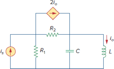
Design a problem to provide better understanding of nodal analysis.
Explanation of Solution
Given data:
Refer to Figure 10.61 in the textbook for nodal analysis.
Formula used:
Write the expression to calculate impedance of the inductor.
Here,
Write the expression to calculate impedance of the capacitor.
Here,
Write the general representation of sinusoidal function.
Here,
Write the general expression to phasor transform of sinusoidal function from time domain to frequency domain.
Here,
Write the polar form representation of frequency domain.
Calculation:
In Figure 10.61, consider the value of source current
Comparing assumed source current with equation (3), the magnitude, angular frequency, and phase angle of source current are
Substitute
Substitute
Substitute
The frequency domain representation of given figure for assumed values is shown in Figure 1.
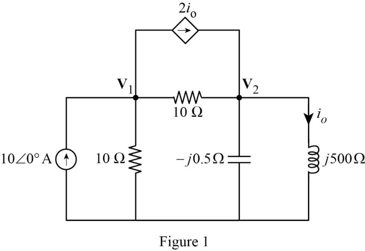
Apply Kirchhoff’s current law at node
From Figure 1, write the expression for current
Substitute equation (6) in (5).
Apply Kirchhoff’s current law at node
Substitute equation (6) in (8).
Rearrange equation (7).
Substitute equation (7) in (9).
Simplify the equation as follows.
Substitute
Represent the current in time domain.
Conclusion:
Thus, a problem has been designed to provide better understanding of nodal analysis.
Want to see more full solutions like this?
Chapter 10 Solutions
EBK FUNDAMENTALS OF ELECTRIC CIRCUITS


- The oscillator circuit in Fig. 10.134 uses an ideal op amp. (a) Calculate the minimum value of R, that will cause oscillation to occur. (b) Find the frequency of oscillation. 1 M2 100 k2 ww R. 10 μΗ 2 nF 10 k2 wwarrow_forward| Steady-State Analysis quivalent at terminals a-l 6Ω j2 Q ell e 10.24 ctice Prob. 10.8. +arrow_forwardDetermine the Norton equivalent of the circuit in Fig. 10.30 as seen from terminals a-b. Use the equivalent to find I ww IA -130 wwH ww 10A 10/0 V O 290 Aarrow_forward
- 10:45 1 .III 5G Done Series Parallel Practice Problems 1 of 7 Series/Parallel Circuits Practice Problems For each circuit provided, fully solve and complete the associated table. 1. 12 GOV RS 2000 R4 3000 R3 350 R(Q) V(v) I(A) P(W) 22222 300 300 35 15 200 Total R(Q) V(v) I(A) P(W)arrow_forwardUse the figure to design a problem that helps other students to better understand nodal analysis.arrow_forward63. Use phasors and nodal analysis on the circuit of Fig. 10.65 to find V2. j3 0 5/90 A (* 30 O 10/0 Aarrow_forward
- (ACADEMIC) 8205828page%3D1 The equivalent resistance RAR (in the figure) is: A O 62. 10. BO 10. 12. b. not possible to compute without Y to Delta conversion. C. bere to search S3一4arrow_forwardFor the circuit shown, find the Thevenin and Norton equivalent at terminal AB. 25 V 10.02 2002> 1002 www . Ad B in 1052arrow_forwardCalculate current I, in the circuit of Fig. 10.11. Answer: 2.538/5.943° A. Practice Problem 10.4 1012 www -j4Q j8Q2 25/0° V 592 -1692 Figure 10.11 For Practice Prob. 10.4. 1/0° Aarrow_forward
- Determine the Norton equivalent of the circuit in Fig. 10.30 as seen from terminals a-b. Use the equivalent to find Io.arrow_forwardPRACTICE PROBLEM 10.7 Find I, in the circuit of Fig. 10.19 using the concept of source transfor- mation. 4/90° A 292 jlQ wwwm Answer: 3.288/99.46° A. 4Ω -j3 92 j5 92 Figure 10.19 For Practice Prob. 10.7. 192 -j2 92arrow_forwardQ.4) For the power electronics circuit shown below, sketch the output voltage waveform (Vo) and hence find its average value. a = 80° R - 102 40V Vs = 200 sin cot Vo R = 102arrow_forward
 Introductory Circuit Analysis (13th Edition)Electrical EngineeringISBN:9780133923605Author:Robert L. BoylestadPublisher:PEARSON
 Delmar's Standard Textbook Of ElectricityElectrical EngineeringISBN:9781337900348Author:Stephen L. HermanPublisher:Cengage Learning
 Programmable Logic ControllersElectrical EngineeringISBN:9780073373843Author:Frank D. PetruzellaPublisher:McGraw-Hill Education
 Fundamentals of Electric CircuitsElectrical EngineeringISBN:9780078028229Author:Charles K Alexander, Matthew SadikuPublisher:McGraw-Hill Education
 Electric Circuits. (11th Edition)Electrical EngineeringISBN:9780134746968Author:James W. Nilsson, Susan RiedelPublisher:PEARSON
 Engineering ElectromagneticsElectrical EngineeringISBN:9780078028151Author:Hayt, William H. (william Hart), Jr, BUCK, John A.Publisher:Mcgraw-hill Education,