
Loose Leaf for Shigley's Mechanical Engineering Design Format: LooseLeaf
10th Edition
ISBN: 9780073399652
Author: BUDYNAS
Publisher: Mcgraw Hill Publishers
expand_more
expand_more
format_list_bulleted
Concept explainers
Videos
Textbook Question
Chapter 10, Problem 20P
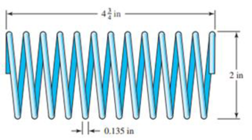
Consider the steel spring in the illustration.
- (a) Find the pitch, solid height, and number of active turns.
- (b) Find the spring rate. Assume the material is A227 HD steel.
- (c) Find the force Fs required to close the spring solid.
- (d) Find the shear stress in the spring due to the force Fs.
Problem 10-20
Expert Solution & Answer
Want to see the full answer?
Check out a sample textbook solution
Students have asked these similar questions
Not all springs are made in a conventional way. Consider the special steel spring in the illustration.
(a) Find the pitch, solid height, and number of active turns.
(b) Find the spring rate. Assume the material is A227 HD steel.
(c) Find the force F, required to close the spring solid.
(d) Find the shear stress in the spring due to the force F,.
120 mm-
-3.4 mm
50 mm
Consider the special steel spring in the illustration.
(a) Find the pitch, solid height, and number of active turns.
(b) Find the spring rate. Assume the material is A227 HD steel.
(c) Find the force Fs required to close the spring solid.
(d) Find the shear stress in the spring due to the force Fs.
150mm
75mm
-e Smm
6-28 The figure shows a formed round-wire cantilever spring subjected to a varying force.
The hardness tests made on 50 springs gave a minimum hardness of 400 Brinell. It is
apparent from the mounting details that there is no stress concentration. A visual
inspection of the springs indicates that the surface finish corresponds closely to a hot-
rolled finish. Ignore curvature effects on the bending stress. What number of applica-
tions is likely to cause failure? Solve using:
(a) Goodman criterion.
(b) Gerber criterion.
= 40 lbf
max
12 in-
= 20 lbf
min
Problem 6-28
Chapter 10 Solutions
Loose Leaf for Shigley's Mechanical Engineering Design Format: LooseLeaf
Ch. 10 - Within the range of recommended values of the...Ch. 10 - It is instructive to examine the question of the...Ch. 10 - A helical compression spring is wound using...Ch. 10 - The spring in Prob. 10-3 is to be used with a...Ch. 10 - A helical compression spring is made with...Ch. 10 - A helical compression spring is to be made of...Ch. 10 - A helical compression spring is made of hard-drawn...Ch. 10 - The spring of Prob. 107 is to be used with a...Ch. 10 - 109 to 1019 Listed in the tables are six springs...Ch. 10 - 109 to 1019 Listed in the tables are six springs...
Ch. 10 - 10-9 to 10-19 Listed in the tables are six springs...Ch. 10 - Prob. 12PCh. 10 - 10-9 to 10-19 Listed in the tables are six springs...Ch. 10 - 10-9 to 10-19 Listed in the tables are six springs...Ch. 10 - 10-9 to 10-19 Listed in the tables are six springs...Ch. 10 - 10-9 to 10-19 Listed in the tables are six springs...Ch. 10 - Prob. 17PCh. 10 - 10-9 to 10-19 Listed in the tables are six springs...Ch. 10 - 10-9 to 10-19 Listed in the tables are six springs...Ch. 10 - Consider the steel spring in the illustration. (a)...Ch. 10 - A static service music wire helical compression...Ch. 10 - Solve Prob. 1021 by iterating with an initial...Ch. 10 - A holding fixture for a workpiece 37.5 mm thick at...Ch. 10 - Solve Prob. 10-23 by iterating with an initial...Ch. 10 - A compression spring is needed to fit over a...Ch. 10 - A compression spring is needed to fit within a...Ch. 10 - A helical compression spring is to be cycled...Ch. 10 - The figure shows a conical compression helical...Ch. 10 - A helical coil compression spring is needed for...Ch. 10 - Solve Prob. 10-30 using the Goodman-Zimmerli...Ch. 10 - Solve Prob. 10-30 using the Sines-Zimmerli...Ch. 10 - Design the spring of Ex. 10-5 using the...Ch. 10 - Solve Prob. 10-33 using the Goodman-Zimmerli...Ch. 10 - A hard-drawn spring steel extension spring is to...Ch. 10 - The extension spring shown in the figure has...Ch. 10 - Design an infinite-life helical coil extension...Ch. 10 - Prove Eq. (10-40). Hint: Using Castigliunos...Ch. 10 - The figure shows a finger exerciser used by...Ch. 10 - The rat trap shown in the figure uses two...Ch. 10 - Prob. 41PCh. 10 - Prob. 42PCh. 10 - Figure 10-13b shows a spring of constant thickness...
Knowledge Booster


Learn more about
Need a deep-dive on the concept behind this application? Look no further. Learn more about this topic, mechanical-engineering and related others by exploring similar questions and additional content below.Similar questions
- Compare the angle of twist 1 for a thin-walled circular tube (see figure) calculated from the approximate theory for thin-walled bars with the angle of twist 2 calculated from the exact theory of torsion for circular bars, Express the ratio 12terms of the non-dimensional ratio ß = r/t. Calculate the ratio of angles of twist for ß = 5, 10, and 20. What conclusion about the accuracy of the approximate theory do you draw from these results?arrow_forwardRepeat Problem 10.3-15 using L = 3.5 m, max = 3 mm, and EI = 800 kN·m2.arrow_forwardConsider the steel spring in the illustration. (a) Find the pitch, solid height, and number of active turns. (b) Find the spring rate. Assume the material is A227 HD steel. (c) Find the force Fs required to close the spring solid. (d) Find the shear stress in the spring due to the force Fs. -4클 in 2 in -e 0.135 inarrow_forward
- After recording the applied twisting moment and resulted angle, fill the following table MT (N.m) T. MPa (degree) (rad.) Now, the twisting moment-twisting angle and shear stress-shear strain curves can be plotted, then determine maximum shear stress, shear stress at proportional limit and modulus of rigidity. 4-6 Problem The following torsion test data were obtained for AA6061-T6 aluminum alloy has a round cross section with 30mm outer diameter, 0 inner diameter and 100 length. 0 32 130 Twisted angle (): 0 1 Torque (N.m): 286 347 487 5.5 591 786 910 1105 1163 1235 1222 3.5 6.5 7.5 9. 10.5 13.5 16.5 21.5 25.5 > Plot the torque-twisted angle curve and determine the proportional limit on it. Plot the shear stress-strain curve the determine the shearing strength and modulus of rigidity. Prof. Adnan N. Abood Asst. Lec. Zainah Waheed 25arrow_forwardwire- 15 mm R Wire clip 3. The figure shows a finger exerciser. It is based on torsion spring. The number of turns is 3 handle. turn. The spring mean diameter is 30mm. The 108 mm 84 mm modulus of elasticity E=210000 MPa. Its working range is 20 degree. If the human finger force is F 50N, calculate the suitable wire diameter. Then, calculate the bending stresses in this spring. 32Fr 4c? - с -1 K; = 4C(C – 1) c=? 64M DN, C = o = K;- nd 64FT DN, d'E d4Earrow_forwardDesign a helical compression spring to be used in a cam and follower mechanism made of oil tempered carbon steel, to sustain a load, which varies from 400 N to 980 N. The spring index is 6.8 and the design factor of safety is 1.25. If the yield stress in shear is 770 MPa and endurance stress in shear is 350 MPa, find: 4. Free length of the spring. 5. Ks= shear factor 6. whals factor The compression of the spring at the maximum load is 30 mm. The modulus of rigidity for the spring material may be taken as 80 kN/mm-.arrow_forward
- The free end of a torsional spring deflects through 90° when subjected to a torque of 4 N-m. The spring index is 6. Determine the coil wire diameter and number of turns with the following data : Modulus of rigidity 80 GPa ; Modulus of elasticity = 200 GPa; Allowable stress = 500 MPa.arrow_forward- A flat spiral steel spring is to give a maximum torque of 1500 N-mm for a maximum stress of 1000 MPa. • Find the thickness and length of the spring to give three complete turns of motion, when the stress . decreases from 1000 to zero. The width of the spring strip is 12 mm. The Young's modulus for the material of the strip is 200 kN/mm2.arrow_forwardGear shaft ABCDE is subjected to the torques shown in the figure. Find the internal torque in each seg- ment, and then plot the torsional moment diagram. Assume that the spacing between gears is constant, i.e., 10 in. T1 = T2 = 1000 lb-in. 500 lb-in. A B T3 = 800 Ib-in. C Ta = 500 lb-in. d = 1.0 in. D T; = 800 lb-in. Earrow_forward
- A mechanism used in a punchingmachinery consists of a tension spring assembled with a preload of 30 N. The wire diameter of spring is 2 mm with a spring index of 7. The spring has 10active coils. The spring wire is hard drawn and oil tempered having the following material properties:Design shear stress = 780 MPa Modulus of rigidity = 80 kN/mm2Identify (a) the initial torsional shear stress in the wire, (b) the spring rate, and (c) the force to cause the body of the spring to reach its yield strength.arrow_forwardPROBLEM: 5 A helical valve spring is to be designed for an operating load range of 90N to 195N. The maximum deflection of the spring for this load range is 7.5 mm. Assuming a spring index of 9, a permissible shear stress of 550 N/mm2 for the material and the modulus of rigidity of 0.85x10⁵ N/mm2. Determine the dimensions of the spring. (i.e. Diameter of the spring wire ,Mean coil diameter, Outer diameter of the spring, number of active turn and free length of the spring). Assume the spring coil is squared and ground.arrow_forwardDesign a helical compression spring to be used in a cam and follower mechanism made of oil tempered carbon steel, to sustain a load, which varies from 400 N to 980 N. The spring index is 6.8 and the design factor of safety is 1.25. If the yield stress in shear is 770 MPa and endurance stress in shear is 350 MPa, find: 1. Size of the spring wire, 2. Diameters of the spring, 3. Number of turns of the spring, and The compression of the spring at the maximum load is 30 mm. The modulus of rigidity for the spring material may be taken as 80 kN/mm. Iarrow_forward
arrow_back_ios
SEE MORE QUESTIONS
arrow_forward_ios
Recommended textbooks for you
 Mechanics of Materials (MindTap Course List)Mechanical EngineeringISBN:9781337093347Author:Barry J. Goodno, James M. GerePublisher:Cengage Learning
Mechanics of Materials (MindTap Course List)
Mechanical Engineering
ISBN:9781337093347
Author:Barry J. Goodno, James M. Gere
Publisher:Cengage Learning
moment of inertia; Author: NCERT OFFICIAL;https://www.youtube.com/watch?v=A4KhJYrt4-s;License: Standard YouTube License, CC-BY