
Control Systems Engineering
7th Edition
ISBN: 9781118170519
Author: Norman S. Nise
Publisher: WILEY
expand_more
expand_more
format_list_bulleted
Concept explainers
Videos
Textbook Question
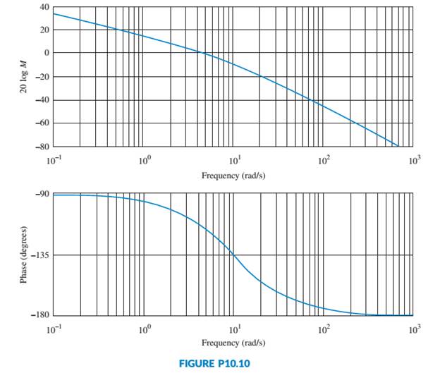
Chapter 10, Problem 32P
For the Bode plots shown in Figure P10.10, determine the transfer function by hand or via MATLAB. [Section: 10.13]
Expert Solution & Answer
Want to see the full answer?
Check out a sample textbook solution
Students have asked these similar questions
Figure 1 shows an electrical system comprising a series RLC circuit and input voltagesource ein(t).(a) Derive the input-output equation with output y = I and input u = ein(t).
(b) Using the derived input-output equation, drive the system transfer function G(s)that relates output to input. Use the following numerical values for the electrical systemparameters: resistance R = 2Ω, inductance L = 0.25H, and capacitance C = 0.4F.
(c) Using the derived transfer function, derive the time-domain ordinary differentialequation for the input-output equation of this electrical system.
(d) Draw the complete block diagram of this series RLC circuit using the derived transferfunction.
1. Give an example of open loop and closed loop system (one example each). Also state the input, control system, feedback and output parameter.
Example.
1. Open Loop - Water Heater:
Input - Water Temperature (Cold)
System - Heating Element
Output - Water Temperature (Hot)
2. Closed Loop - Air-conditioning System
Input - Desired Room Temperature
Control - Motor controller/Compressor/ACU
Feedback - Temperature Sensing
Output - Room Temperature
Sketch the level response for a bathtub with cross-sectional area of 8 ft 2 as a function of time for the following sequence of events; assume an initial level of 0.5 ft with the drain open. The inflow and outflow are initially equal to2ft3/min.(a)The drain is suddenly closed, and the inflow remains con-stant for 3 min (0≤t≤3).(b)The drain is opened for 15 min; assume a time constant in a linear transfer function of 3 min, so a steady state is essentially reached (3≤t≤18) (c)The inflow rate is doubled for 6 min (18≤t≤24).(d)The inflow rate is returned to its original value for 16 min(24≤t≤40).
Chapter 10 Solutions
Control Systems Engineering
Ch. 10 - Prob. 1RQCh. 10 - Prob. 2RQCh. 10 - Prob. 3RQCh. 10 - Briefly describe how to obtain the frequency...Ch. 10 - Prob. 5RQCh. 10 - Each pole of a system contributes how much of a...Ch. 10 - Prob. 7RQCh. 10 - Prob. 8RQCh. 10 - Prob. 9RQCh. 10 - What is the major difference between Bode...
Ch. 10 - Prob. 11RQCh. 10 - Prob. 12RQCh. 10 - Prob. 13RQCh. 10 - 14. What is a Nyquist diaoram?
Ch. 10 - Prob. 15RQCh. 10 - 16. When sketching a Nyquist diagram, what must be...Ch. 10 - Prob. 17RQCh. 10 - Prob. 18RQCh. 10 - Prob. 19RQCh. 10 - Prob. 20RQCh. 10 - Prob. 21RQCh. 10 - Prob. 22RQCh. 10 - Prob. 23RQCh. 10 - Prob. 24RQCh. 10 - Prob. 25RQCh. 10 - Prob. 26RQCh. 10 - Prob. 1PCh. 10 - Prob. 7PCh. 10 - Prob. 14PCh. 10 - For each closed-loop system with the following...Ch. 10 - Prob. 27PCh. 10 - For the Bode plots shown in Figure P10.10,...
Knowledge Booster


Learn more about
Need a deep-dive on the concept behind this application? Look no further. Learn more about this topic, mechanical-engineering and related others by exploring similar questions and additional content below.Similar questions
- For the given close-loop system transfer function, determine its stability using Routh-Hurwitz Test for Stability.1. What is the stability of the system? (Stable, Unstable, Marginally Stable)arrow_forwarda)is the aircraft stable about the equilibrium represented by the transfer function? b) Using proportional feedback,what is the range of acceptable gains for the closed loop systen to be stable? c) Design a feedback control system that allows the pilot to command a pitch angle with overshoot less than or equal to 4.15% and a natural frequency of greater than or equal to 0.99 rad/s d) Design a feedback control system that allows the pilot to command a pitch angle with the same overshoot and a natural frequency of one half the system in part c.arrow_forward1.block diagram physical meaning and the time response for different inputsarrow_forward
- Q.1 - The open loop transfer function for a unity - feedback systemis G(s)= XL‘ 7xs and r(t)=3t determine steady state error.If it is desired to reduce this existing error by 7% fined new value of gain of the system.arrow_forwardA stock-flow system models the level of water in a lake. Near a certain equilibrium point, there are three feedback loops: an amplifying feedback loop with strength of +0.55 per month, a stabilizing feedback loop with strength of -0.09 per month, and an amplifying feedback loop with strength of +0.79 per month. Calculate the strength of the overall feedback.arrow_forwardWrite the transfer function of figure 1.3 for the given values, add the BODE diagram andpoles-zeros graph.Use the keyboard, do not write by handarrow_forward
- Given the system equipped with unitary feedback, whose direct branch transfer function is: Design a PID controller with one of the Ziegler-Nichols methods.arrow_forwarda)If the system has a transfer function of the form G_P (s)=H(s)/(V_m (s) )=μ/(1+Ts) where µ is the gain and T is the time constant, calculate values for µ and T for the case where the valve is at position 3. Hints: Use the constants and information in table 1. The dynamics of the water tank can be found by applying the continuity equation: qin - qout = rate of change in water tankarrow_forwardThe close loop system block diagram is given below .Find the transfer function of the given system.arrow_forward
- Reduce the block diagram shown in Figure below to a single transfer function, T(s) = C(s)/R(s) Use the block diagram reduction method.arrow_forwardDo not do the matlab partarrow_forwardThe ratio of output to input of a system in Laplace domain is known as Transfer function . Select one: True Falsearrow_forward
arrow_back_ios
SEE MORE QUESTIONS
arrow_forward_ios
Recommended textbooks for you
 Principles of Heat Transfer (Activate Learning wi...Mechanical EngineeringISBN:9781305387102Author:Kreith, Frank; Manglik, Raj M.Publisher:Cengage Learning
Principles of Heat Transfer (Activate Learning wi...
Mechanical Engineering
ISBN:9781305387102
Author:Kreith, Frank; Manglik, Raj M.
Publisher:Cengage Learning
Introduction to Undamped Free Vibration of SDOF (1/2) - Structural Dynamics; Author: structurefree;https://www.youtube.com/watch?v=BkgzEdDlU78;License: Standard Youtube License