
Electronics Fundamentals: Circuits, Devices & Applications
8th Edition
ISBN: 9780135072950
Author: Thomas L. Floyd, David Buchla
Publisher: Prentice Hall
expand_more
expand_more
format_list_bulleted
Videos
Textbook Question
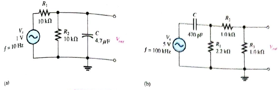
Chapter 10, Problem 38P
Each of the capacitors in Figure 10-86 has developed a leakage resistance of
Determine the output voltage under this condition for each circuit.
Expert Solution & Answer
Want to see the full answer?
Check out a sample textbook solution
Students have asked these similar questions
The total inductance in this circuit is _______.
5.09 mH
95 mH
5.09 H
95 H
For which frequency the current is 37 ° behind the voltage in the R = 50, L = 10mH series circuit.
Two capacitors are in series. Their values are 47 pF and 33 pF. The composite
value is:
A. 80 pF.
B. 47 pF.
C. 33 pF.
D. 19 pF.
Chapter 10 Solutions
Electronics Fundamentals: Circuits, Devices & Applications
Ch. 10 - In a series RC circuit, the impedance increases...Ch. 10 - In a series RC lag circuit, the output voltage is...Ch. 10 - Admittance is the reciprocal of susceptance.Ch. 10 - In a parallel RC circuit, as frequency is...Ch. 10 - The phase angle of an RC circuit is measured...Ch. 10 - Prob. 6TFQCh. 10 - Prob. 7TFQCh. 10 - The power factor is equal to the tangent of the...Ch. 10 - A purely resistive circuit has a power factor of...Ch. 10 - Prob. 10TFQ
Ch. 10 - Prob. 1STCh. 10 - Prob. 2STCh. 10 - Prob. 3STCh. 10 - When the frequency of the voltage applied to a...Ch. 10 - Prob. 5STCh. 10 - Prob. 6STCh. 10 - The voltages in Problem 6 are measured at a...Ch. 10 - Prob. 8STCh. 10 - Prob. 9STCh. 10 - When the frequency of the source voltage is...Ch. 10 - Prob. 11STCh. 10 - Prob. 12STCh. 10 - Prob. 13STCh. 10 - Prob. 14STCh. 10 - If the bandwidth or a certain low-pass filter is 1...Ch. 10 - Prob. 1TSCCh. 10 - Prob. 2TSCCh. 10 - Prob. 3TSCCh. 10 - Determine the cause for each set of symptoms....Ch. 10 - Determine the cause for each set of symptoms....Ch. 10 - An 8 kHz sinusoidal voltage is applied to a series...Ch. 10 - What is th waveshape of the current in the circuit...Ch. 10 - Find the impedance of each circuit in Figure...Ch. 10 - Determine the impedance and the phase angle in...Ch. 10 - For the circuit of Figure 10-69, determine the...Ch. 10 - Repeat Problem 5 for C=0.0047F.Ch. 10 - Calculate the total current in each circuit of...Ch. 10 - Repeat Problem 7 for the circuits in Figure 10-68.Ch. 10 - For the circuit in Figure 10-70, draw the phase or...Ch. 10 - For the circuit in Figure 10-71, determine the...Ch. 10 - To what value must the rheostat be set in Figure...Ch. 10 - For the lag circuit in Figure 10-73, determine the...Ch. 10 - Repeat Problem 12 for the lead circuit in Figure...Ch. 10 - Determine the impedance for the circuit in Figure...Ch. 10 - Determine the impedance and the phase angle in...Ch. 10 - Repeat Problem 15 for the following frequencies:...Ch. 10 - Determine the impedance and phase angle in Figure...Ch. 10 - For the circuit in Figure 10-78, find all the...Ch. 10 - For the parallel circuit in Figure 10-79, find...Ch. 10 - For the circuit in Figu 10-80, determine the...Ch. 10 - Repeat Problem 20forR=4.7k,C=0.047F,andf=500Hz.Ch. 10 - Convert the circuit in Figure 10-81 to an...Ch. 10 - Determine the voltages across each element in...Ch. 10 - Is the circuit in Figure 10-82 predominantly...Ch. 10 - Find the current through each branch and the total...Ch. 10 - For the circuit in Figure 10-83, determine the...Ch. 10 - In a certain seris RC circuit, the true power is 2...Ch. 10 - In Figure 10-71, what is the true power and the...Ch. 10 - What is the power factor for the circuit of Figure...Ch. 10 - Determine Ptrue, Pr, Pa,andPF for the circuit in...Ch. 10 - The lag circuit in Figure 10-73 also acts as a...Ch. 10 - Plot the frequency response curve for the circuit...Ch. 10 - Draw the voltage phasor diagram for each circuit...Ch. 10 - Thr rms value of the signal voltage out of...Ch. 10 - Determine the cutoff frequency for each circuit in...Ch. 10 - Determine the bandwidth of the circuit in Figure...Ch. 10 - Assume that the capacitor in Figure 10-85 is...Ch. 10 - Each of the capacitors in Figure 10-86 has...Ch. 10 - Determine the output voltage for the circuit in...Ch. 10 - Determine the output voltage for the circuit in...Ch. 10 - A single 240V,60Hz source drives two loads. Load A...Ch. 10 - What value of coupling capacitor is required in...Ch. 10 - Determine the value of R1 required to get a phase...Ch. 10 - Draw the voltage and current phasor diagram for...Ch. 10 - A certain load dissipates 1.5kW of power with an...Ch. 10 - Deteine the series element or element that are in...Ch. 10 - Determine the value of C2 in Figure 10-91 when...Ch. 10 - Draw the schematic for the circuit in Figure 10-92...Ch. 10 - Open file P10-49; files are found at...Ch. 10 - Open file P10-50. Determine if there is a fault...Ch. 10 - www.prenhall.com/floyd. Open file P10-51....Ch. 10 - www.prenhall.com/floyd. Open file P10-52....Ch. 10 - www.prenhall.com/floyd. Open file P10-53....Ch. 10 - www.prenhall.com/floyd. Open file P10-54....
Knowledge Booster


Learn more about
Need a deep-dive on the concept behind this application? Look no further. Learn more about this topic, electrical-engineering and related others by exploring similar questions and additional content below.Similar questions
- In an R-L series circuit, the apparent power is 560 VA, PF = 62%. Find reactive power.arrow_forwardWhat is the value of capacitance that needs to be connected in a parallel configuration to the load in order to correct the pf source to 0.94 lagging. Frequency f= 129 Hzarrow_forwardA) What is the capacitor that must be added to this circuit to get a power factor of .90 600V 60HZ 10.8KW 8.2KVAR B) What is the total current Before the correction? C) What is the total current After the correction?arrow_forward
- Find the current through the capacitor of (-j5) capacitance reactance using MESH ANALYSIS. Final answer should be: 0.80 angle 26.89arrow_forwardShow all steps and working please. A 250 μF capacitor is inserted in parallel with the supply producing a new improved power factor of 0.9345.arrow_forwardA series resistive capacitive circuit contains 2 resistor and 2 capacitors. The resistors are 39 and 56 The capacitors have a capacitive reactance of 80 and 40 What is the total impedance ?arrow_forward
- A 35uf capacitor is connected to a 60 Hz 120v supplyWhat is the Xc of the capacitor?arrow_forwardA RL series circuit has an apparent power of 650 VA and true power of 375 watts. What is the reactive power in the circuit?arrow_forwardAn RLC parallel circuit has an applied voltage of 208 V. R = 68 Ω, XL = 87 Ω, and XC = 81 Ω. What is the power factor? 0.684 0.835 0.998 0.788arrow_forward
arrow_back_ios
SEE MORE QUESTIONS
arrow_forward_ios
Recommended textbooks for you
 Power System Analysis and Design (MindTap Course ...Electrical EngineeringISBN:9781305632134Author:J. Duncan Glover, Thomas Overbye, Mulukutla S. SarmaPublisher:Cengage Learning
 Delmar's Standard Textbook Of ElectricityElectrical EngineeringISBN:9781337900348Author:Stephen L. HermanPublisher:Cengage Learning
Power System Analysis and Design (MindTap Course ...
Electrical Engineering
ISBN:9781305632134
Author:J. Duncan Glover, Thomas Overbye, Mulukutla S. Sarma
Publisher:Cengage Learning
Delmar's Standard Textbook Of Electricity
Electrical Engineering
ISBN:9781337900348
Author:Stephen L. Herman
Publisher:Cengage Learning
02 - Sinusoidal AC Voltage Sources in Circuits, Part 1; Author: Math and Science;https://www.youtube.com/watch?v=8zMiIHVMfaw;License: Standard Youtube License