Concept explainers
Videos
(a)
The rotational kinetic energy.
(a)
Answer to Problem 54P
The rotational kinetic energy for the system is
Explanation of Solution
Redraw the figure P10.54.
Consider that the vertically standing to be initial position and horizontal to be the final position.
Write the equation for conservation of energy.
Here,
From the law of conservation of energy, gain in rotational kinetic energy equals to loss in gravitational potential energy for the given system.
Write the expression for rotational kinetic energy.
Here,
Write the expression for loss in gravitational potential energy for sphere.
Here,
Write the expression for loss in gravitational potential energy for rod.
Here,
Substitute
Conclusion:
Substitute
Thus, the rotational kinetic energy for the system is
(b)
The angular speed of the rod and ball.
(b)
Answer to Problem 54P
The angular speed of the ball and the rod is
Explanation of Solution
Write the expression for moment of inertia of sphere at center.
Here,
Write the expression for the parallel axis theorem for moment of inertia at point
Here,
Substitute
Write the expression for moment of inertia of rod at point
Here,
Write the expression for net moment of inertia for the whole system.
Here,
Substitute
Write the expression for rotational kinetic energy.
Here,
Simply the above equation for value of
Conclusion:
Substitute
Substitute
Thus, the angular speed of the ball and the rod is
(c)
Thelinear speed of the center of mass of the ball.
(c)
Answer to Problem 54P
The linear speed of the ball of center of mass is
Explanation of Solution
Write the expression for linear speed of the ball.
Here,
Substitute
Here,
Conclusion:
Substitute
Thus, the linear speed of the ball of center of mass is
(d)
Compare the speed with the speed had the ball fallen freelythrough the same distance of
(d)
Answer to Problem 54P
The rod pulls the sphere down together while rotating by the speed factor
Explanation of Solution
Loss in gravitational potential energy will be equal to gain in kinetic energy.
Write the expression for the conservation of energy.
Write the expression for loss in gravitational potential energy for sphere.
Here,
Write the expression for gain kinetic energy.
Here,
Substitute
Write the expression for the ratio of new speed to the original speed.
Here,
Conclusion:
Substitute
Substitute
Thus, the rod pulls the sphere down together while rotating by more speed than in direct falling by the factor of
Want to see more full solutions like this?
Chapter 10 Solutions
Physics: for Science.. With Modern. -Update (Looseleaf)


- Review. An object with a mass of m = 5.10 kg is attached to the free end of a light string wrapped around a reel of radius R = 0.250 m and mass M = 3.00 kg. The reel is a solid disk, free to rotate in a vertical plane about the horizontal axis passing through its center as shown in Figure P10.45. The suspended object is released from rest 6.00 m above the floor. Determine (a) the tension in the string, (b) the acceleration of the object, and (c) the speed with which the object hits the floor. (d) Verify your answer to part (c) by using the isolated system (energy) model. Figure P10.45arrow_forwardThe angular momentum vector of a precessing gyroscope sweeps out a cone as shown in Figure P11.31. The angular speed of the tip of the angular momentum vector, called its precessional frequency, is given by p=/I, where is the magnitude of the torque on the gyroscope and L is the magnitude of its angular momentum. In the motion called precession of the equinoxes, the Earths axis of rotation processes about the perpendicular to its orbital plane with a period of 2.58 104 yr. Model the Earth as a uniform sphere and calculate the torque on the Earth that is causing this precession. Figure P11.31 A precessing angular momentum vector sweeps out a cone in space.arrow_forwardA uniform, hollow, cylindrical spool has inside radius R/2, outside radius R, and mass M (Fig. P10.47). It is mounted so that it rotates on a fixed, horizontal axle. A counterweight of mass m is connected to the end of a string wound around the spool. The counterweight falls from rest at t = 0 to a position y at time t. Show that the torque due to the friction forces between spool and axle is f=R[m(g2yt2)M5y4t2] Figure P10.47arrow_forward
- A disk with moment of inertia I1 rotates about a frictionless, vertical axle with angular speed i. A second disk, this one having moment of inertia I2 and initially not rotating, drops onto the first disk (Fig. P10.50). Because of friction between the surfaces, the two eventually reach the same angular speed f. (a) Calculate f. (b) Calculate the ratio of the final to the initial rotational energy. Figure P10.50arrow_forwardA rigid, massless rod has three particles with equal masses attached to it as shown in Figure P11.37. The rod is free to rotate in a vertical plane about a frictionless axle perpendicular to the rod through the point P and is released from rest in the horizontal position at t = 0. Assuming m and d are known, find (a) the moment of inertia of the system of three particles about the pivot, (b) the torque acting on the system at t = 0, (c) the angular acceleration of the system at t = 0, (d) the linear acceleration of the particle labeled 3 at t = 0, (e) the maximum kinetic energy of the system, (f) the maximum angular speed reached by the rod, (g) the maximum angular momentum of the system, and (h) the maximum speed reached by the particle labeled 2. Figure P11.37arrow_forwardReview. An object with a mass of m = 5.10 kg is attached to the free end of a light string wrapped around a reel of radius R = 0.250 m and mass M = 3.00 kg. The reel is a solid disk, free to rotate in a vertical plane about the horizontal axis passing through its center as shown in Figure P10.29. The suspended object is released from rest 6.00 m above the floor. Determine (a) the tension in the string, (b) the acceleration of the object, and (c) the speed with which the object hits the floor. (d) Verify your answer to part (c) by using the isolated system (energy) model. Figure P10.29arrow_forward
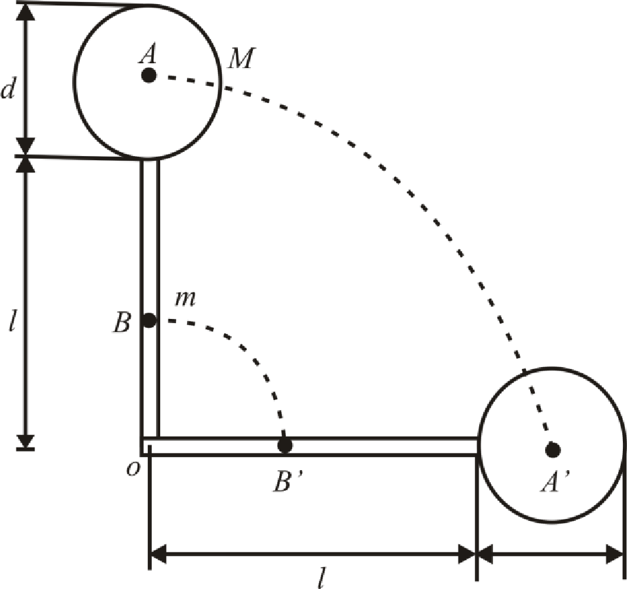
- A long, uniform rod of length L and mass M is pivoted about a frictionless, horizontal pin through one end. The rod is released from rest in a vertical position as shown in Figure P10.65. At the instant the rod is horizontal, find (a) its angular speed, (b) the magnitude of its angular acceleration, (c) the x and y components of the acceleration of its center of mass, and (d) the components of the reaction force at the pivot. Figure P10.65arrow_forwardA ball of mass M = 5.00 kg and radius r = 5.00 cm isattached to one end of a thin,cylindrical rod of length L = 15.0 cm and mass m = 0.600 kg.The ball and rod, initially at restin a vertical position and freeto rotate around the axis shownin Figure P13.70, are nudgedinto motion. a. What is therotational kinetic energy of thesystem when the ball and rodreach a horizontal position? b. What is the angular speed of the ball and rod when they reach a horizontal position? c. What is the linear speed of the centerof mass of the ball when the ball and rod reach a horizontalposition? d. What is the ratio of the speed found in part (c) tothe speed of a ball that falls freely through the same distance? FIGURE P13.70arrow_forwardRigid rods of negligible mass lying along the y axis connect three particles (Fig. P10.18). The system rotates about the x axis with an angular speed of 2.00 rad/s. Find (a) the moment of inertia about the x axis, (b) the total rotational kinetic energy evaluated from 12I2, (c) the tangential speed of each particle, and (d) the total kinetic energy evaluated from 12mivi2. (e) Compare the answers for kinetic energy in parts (b) and (d). Figure P10.18arrow_forward
- Figure P10.16 shows the drive train of a bicycle that has wheels 67.3 cm in diameter and pedal cranks 17.5 cm long. The cyclist pedals at a steady cadence of 76.0 rev/min. The chain engages with a front sprocket 15.2 cm in diameter and a rear sprocket 7.00 cm in diameter. Calculate (a) the speed of a link of the chain relative to the bicycle frame, (b) the angular speed of the bicycle wheels, and (c) the speed of the bicycle relative to the road. (d) What pieces of data, if any, are not necessary for the calculations? Figure P10.16arrow_forwardA uniform beam resting on two pivots has a length L = 6.00 m and mass M = 90.0 kg. The pivot under the left end exerts a normal force n1 on the beam, and the second pivot located a distance = 4.00 m from the left end exerts a normal force n2. A woman of mass m = 55.0 kg steps onto the left end of the beam and begins walking to the right as in Figure P10.28. The goal is to find the womans position when the beam begins to tip. (a) What is the appropriate analysis model for the beam before it begins to tip? (b) Sketch a force diagram for the beam, labeling the gravitational and normal forces acting on the beam and placing the woman a distance x to the right of the first pivot, which is the origin. (c) Where is the woman when the normal force n1 is the greatest? (d) What is n1 when the beam is about to tip? (e) Use Equation 10.27 to find the value of n2 when the beam is about to tip. (f) Using the result of part (d) and Equation 10.28, with torques computed around the second pivot, find the womans position x when the beam is about to tip. (g) Check the answer to part (e) by computing torques around the first pivot point. Figure P10.28arrow_forwardAn electric motor turns a flywheel through a drive belt that joins a pulley on the motor and a pulley that is rigidly attached to the flywheel as shown in Figure P10.37. The flywheel is a solid disk with a mass of 80.0 kg and a radius R = 0.625 m. It turns on a frictionless axle. Its pulley has much smaller mass and a radius of r = 0.230 m. The tension Tu in the upper (taut) segment of the belt is 135 N, and the flywheel has a clockwise angular acceleration of 1.67 rad/s2. Find the tension in the lower (slack) segment of the belt. Figure P10.37arrow_forward
 Physics for Scientists and Engineers: Foundations...PhysicsISBN:9781133939146Author:Katz, Debora M.Publisher:Cengage Learning
 Principles of Physics: A Calculus-Based TextPhysicsISBN:9781133104261Author:Raymond A. Serway, John W. JewettPublisher:Cengage Learning
 Physics for Scientists and EngineersPhysicsISBN:9781337553278Author:Raymond A. Serway, John W. JewettPublisher:Cengage Learning
 Physics for Scientists and Engineers with Modern ...PhysicsISBN:9781337553292Author:Raymond A. Serway, John W. JewettPublisher:Cengage Learning