
Concept explainers
Videos
If the input impedance is defined as Zin = Vs/Is, find the input impedance of the op amp circuit in Fig. 10.116 when R1 = 10 kΩ, R2 = 20 kΩ, C1 = 10 nF, C2 = 20 nF, and ω = 5000 rad/s.
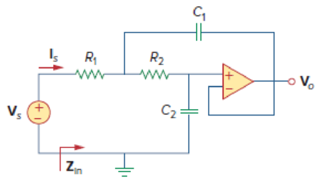
Figure 10.116
Calculate the input impedance
Answer to Problem 73P
The value of input impedance
Explanation of Solution
Given data:
Refer to Figure 10.116 in the textbook for the op amp circuit.
The values of resistance
The values of capacitance
The value of angular frequency
Formula used:
Write the expression to calculate impedance of the capacitor.
Here,
Write the formula for input impedance of the given op amp circuit.
Here,
Calculation:
Substitute
Substitute
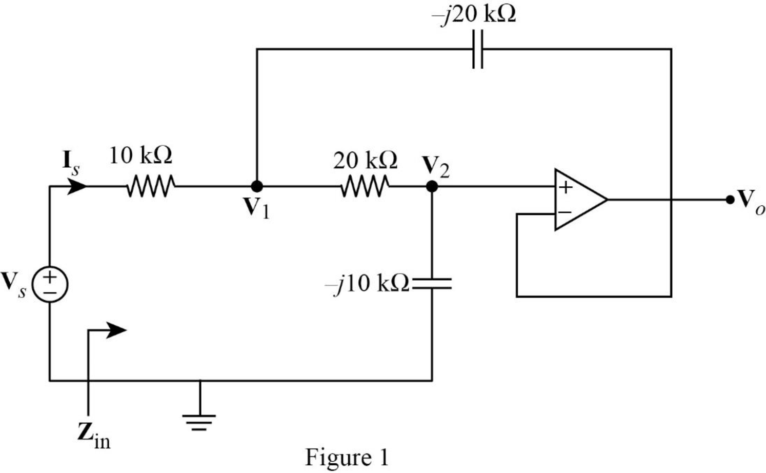
The frequency domain representation of given circuit with the node voltage is shown in Figure 1.
Apply Kirchhoff’s current law at node
According to the properties of an ideal op amp, the voltage appear across the input terminals of the op amp is zero.
The voltage at the inverting terminal will be appear at the non-inverting input terminal. Since the output voltage is fed back to the inverting terminal, the voltage
Substitute equation (4) in (3).
Reduce the equation as follows.
Apply Kirchhoff’s current law at node
Substitute equation (5) and (7).
Simplify the equation as follows.
Substitute equation (7) in (5).
Simplify the above equation as follows.
Substitute equation (8) in (7).
From Figure 1, write the expression for current
Substitute equation (10) in (2).
Conclusion:
Thus, the value of input impedance
Want to see more full solutions like this?
Chapter 10 Solutions
Fundamentals of Electric Circuits


- Determine the Thevenin equivalent of the circuit in Fig. 10.27 as seen from the terminals a-b.arrow_forwardReferring to the circuit of Fig. 10.59, employ phasor-based analysis techniques to determine the two nodal voltages. (Circuit attached in image).arrow_forwardCalculate the output voltages V2 and V3 in the circuit of Fig. 10.72 .arrow_forward
- A receiver connected to an antenna whose resistance is 50Ω has an equivalent noise resistance of 30Ω. Calculate the receiver's noise figure.arrow_forwardA receiver connected to an antenna whose resistance is 50Ω has an equivalent noise resistance of 30Ω. Calculate the equivalent noise temperature.arrow_forwardEmploy phasor analysis techniques to obtain expressions for the two mesh currents i1 and i2 as shown in Fig. 10.61. Circuit attached in image.arrow_forward
 Introductory Circuit Analysis (13th Edition)Electrical EngineeringISBN:9780133923605Author:Robert L. BoylestadPublisher:PEARSON
 Delmar's Standard Textbook Of ElectricityElectrical EngineeringISBN:9781337900348Author:Stephen L. HermanPublisher:Cengage Learning
 Programmable Logic ControllersElectrical EngineeringISBN:9780073373843Author:Frank D. PetruzellaPublisher:McGraw-Hill Education
 Fundamentals of Electric CircuitsElectrical EngineeringISBN:9780078028229Author:Charles K Alexander, Matthew SadikuPublisher:McGraw-Hill Education
 Electric Circuits. (11th Edition)Electrical EngineeringISBN:9780134746968Author:James W. Nilsson, Susan RiedelPublisher:PEARSON
 Engineering ElectromagneticsElectrical EngineeringISBN:9780078028151Author:Hayt, William H. (william Hart), Jr, BUCK, John A.Publisher:Mcgraw-hill Education,