
EBK STATICS AND MECHANICS OF MATERIALS
5th Edition
ISBN: 8220102955295
Author: HIBBELER
Publisher: PEARSON
expand_more
expand_more
format_list_bulleted
Concept explainers
Videos
Textbook Question
Chapter 10.3, Problem 5P
The copper pipe has an outer diameter of 2.50 in. and an inner diameter of 2.30 in. If it is tightly secured to the wall and three torques are applied to it. determine the shear stress developed at points A and B. These points lie on the pipe’s outer surface. Sketch the shear stress on volume elements located at A and B.
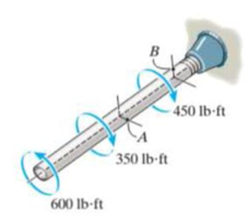
Prob. 10-5
Expert Solution & Answer
Want to see the full answer?
Check out a sample textbook solution
Students have asked these similar questions
The copper pipe has an outer diameter of 2.50 in. and an inner diameter of 2.30 in. If it is tightly secured to the wall and three torques are applied to it, determine the shear stress developed at points A and B. These points lie on the pipe’s outer surface. Sketch the shear stress on volume elements located at A and B.
The copper pipe has an outer diameter of 3 in. and an inner diameter of 2.5 in. If it is tightly secured to the wall at C and a uniformly distributed torque is applied to it as shown, determine the shear stress at points A and B. These points lie on the pipe’s outer surface. Sketch the shear stress on volumeelements located at A and B.
The copper pipe has an outer diameter of 3 in. and an inner diameter of 2.50 in. If it is tightly secured to the wall at C and it is subjected to the uniformly distributed torque along its entire length, determine the absolute maximum shear stress in the pipe. Discuss the validity of this result.
Chapter 10 Solutions
EBK STATICS AND MECHANICS OF MATERIALS
Ch. 10.3 - Determine the internal torque at each section and...Ch. 10.3 - Determine the internal torque at each section and...Ch. 10.3 - Prob. 3PPCh. 10.3 - Prob. 4PPCh. 10.3 - Prob. 1FPCh. 10.3 - The hollow circular shaft is subjected to an...Ch. 10.3 - Prob. 3FPCh. 10.3 - Prob. 4FPCh. 10.3 - Determine the maximum shear stress in the shaft at...Ch. 10.3 - Prob. 6FP
Ch. 10.3 - The solid 50-mm-diameter shaft is subjected to the...Ch. 10.3 - Prob. 8FPCh. 10.3 - Prob. 1PCh. 10.3 - Prob. 2PCh. 10.3 - A shaft is made of an aluminum alloy having an...Ch. 10.3 - The copper pipe has an outer diameter of 40 mm and...Ch. 10.3 - The copper pipe has an outer diameter of 2.50 in....Ch. 10.3 - The solid aluminum shaft has a diameter of 50 mm...Ch. 10.3 - The solid aluminum shaft has a diameter of 50 mm....Ch. 10.3 - The solid 30-mm-diameter shaft is used to transmit...Ch. 10.3 - The solid shaft is fixed to the support at C and...Ch. 10.3 - The link acts as part of the elevator control for...Ch. 10.3 - The assembly consists of two sections of...Ch. 10.3 - The shaft has an outer diameter of 100 mm and an...Ch. 10.3 - Prob. 13PCh. 10.3 - Prob. 14PCh. 10.3 - Prob. 15PCh. 10.3 - Prob. 16PCh. 10.3 - The rod has a diameter of 1 in. and a weight of 10...Ch. 10.3 - Prob. 18PCh. 10.3 - Prob. 19PCh. 10.3 - Prob. 20PCh. 10.3 - Prob. 21PCh. 10.3 - The 60-mm-diametcr solid shaft is subjected to the...Ch. 10.3 - Prob. 23PCh. 10.3 - The 60-mm-diameter solid shaft is subjected to the...Ch. 10.3 - Prob. 25PCh. 10.3 - The pump operates using the motor that has a power...Ch. 10.3 - Prob. 27PCh. 10.3 - Prob. 28PCh. 10.3 - Prob. 29PCh. 10.3 - The gear motor can develop 2 hp when it turns at...Ch. 10.3 - Prob. 31PCh. 10.3 - The 6-hp reducer motor can turn at 1200 rev/min....Ch. 10.3 - Prob. 33PCh. 10.3 - Prob. 34PCh. 10.4 - The 60-mm-diameter steel shaft is subjected to the...Ch. 10.4 - Prob. 10FPCh. 10.4 - The hollow 6061-T6 aluminum shaft has an outer and...Ch. 10.4 - A series of gears are mounted on the...Ch. 10.4 - Prob. 13FPCh. 10.4 - The 80-mm-diameter shaft is made of steel. If it...Ch. 10.4 - The propellers of a ship are connected to an A-36...Ch. 10.4 - Prob. 36PCh. 10.4 - The splined ends and gears attached to the A992...Ch. 10.4 - Prob. 38PCh. 10.4 - The 60-mm-diameter shaft is made of 6061-T6...Ch. 10.4 - The 60-mm-diameter shaft is made of 6061-T6...Ch. 10.4 - Prob. 41PCh. 10.4 - Prob. 42PCh. 10.4 - Gear B supplies 15 kW of power, while gears A, C,...Ch. 10.4 - Prob. 44PCh. 10.4 - The turbine develops 150 kW of power, which is...Ch. 10.4 - Prob. 46PCh. 10.4 - Prob. 47PCh. 10.4 - Prob. 48PCh. 10.4 - The A 992 steel shaft has a diameter of 50 mm and...Ch. 10.4 - The turbine develops 300 kW of power, which is...Ch. 10.4 - Prob. 51PCh. 10.4 - The device shown is used to mix soils in order to...Ch. 10.4 - The 6-in.-diameter L-2 steel shaft on the turbine...Ch. 10.4 - The A-36 hollow steel shaft is 2 m long and has an...Ch. 10.4 - The A-36 solid steel shaft is 3 m long and has a...Ch. 10.4 - Prob. 56PCh. 10.4 - Prob. 57PCh. 10.4 - Prob. 58PCh. 10.4 - The tubular drive shaft for the propeller of a...Ch. 10.4 - The 60-mm diameter solid shaft is made of 2014-T6...Ch. 10.4 - Prob. 61PCh. 10.5 - The steel shaft has a diameter of 40 mm and is...Ch. 10.5 - The A992 steel shaft has a diameter of 60 mm and...Ch. 10.5 - The steel shaft is made from two segments: AC has...Ch. 10.5 - The bronze C86100 pipe has an outer diameter of...Ch. 10.5 - The bronze C86100 pipe has an outer diameter of...Ch. 10.5 - Prob. 67PCh. 10.5 - Prob. 68PCh. 10.5 - The Am1004-T61 magnesium tube is bonded to the...Ch. 10.5 - The Am1004-T61 magnesium tube is bonded to the...Ch. 10.5 - The two shafts are made of A-36 steel. Each has a...Ch. 10.5 - Prob. 72PCh. 10.5 - Prob. 73PCh. 10.5 - Prob. 74PCh. 10.5 - Prob. 75PCh. 10.5 - The composite shaft consists of a mid-section that...Ch. 10.5 - Prob. 77PCh. 10.5 - The tapered shaft is confined by the fixed...Ch. 10.5 - Prob. 79PCh. 10 - The shaft is made of A992 steel and has an...Ch. 10 - The shaft is made of A992 steel and has an...Ch. 10 - The A-36 steel circular tube is subjected to a...Ch. 10 - Prob. 4RPCh. 10 - Prob. 5RPCh. 10 - Prob. 6RPCh. 10 - Prob. 7RPCh. 10 - Prob. 8RPCh. 10 - The 60-mm-diameter shaft rotates at 300 rev/min....
Knowledge Booster


Learn more about
Need a deep-dive on the concept behind this application? Look no further. Learn more about this topic, mechanical-engineering and related others by exploring similar questions and additional content below.Similar questions
- 9-39. Determine the principal stresses acting at point B, which is located just on the web, below the horizontal segment on the cross section. Show the results on a properly oriented element located at this point. Although it is not very accurate, use the shear formula to calculate the shear stress. 12 mm A 150 mm 130 mm- B A -800 mm- 300 mm B -15 mm 6 kN Prob. 9-39 5arrow_forwardThe shaft consists of two sections that are rigidly connected. If the material is elastic perfectly plastic as shown, determine the largest torque T that can be applied to the shaft. Also, draw the shear-stress distribution over a radial line for each section. Neglect the effect of stress concentration.arrow_forwardThe copper pipe has an outer diameter of 50 mm and an inner diameter of 40 mm. It is tightly secured to the wall at A and three torques are applied to it as shown. determine the shear stress at each segment and the absolute maximum shear stress developed in the pipe. 80 N-m 20 N-m 30 N-marrow_forward
- The copper pipe has an outer diameter of 40 mm and an inner diameter of 37 mm. If it is tightly secured to the wall at A and 3 torques are applied to it as shown, determine the absolute maximum shear stress developed in the pipe. Given the shear modulus G = 37 GPa for copper and the segmental lengths of the pipe, calculate the angle of twist of point D with respect to point A| B Length: AB = 0.6 m ´ 30 N-m 20 N-m BC = 0.6 m CD = 1.2 m 80 N-marrow_forwardThe copper pipe has an outer diameter of 40 mm and an inner diameter of 37 mm. If it is tightly secured to the wall and three torques are applied to it, determine the absolute maximum shear stress developed in the pipe.arrow_forward= 5-6. The solid shaft has a diameter of 0.75 in. If it is subjected to the torques shown, determine the maximum shear stress developed in regions BC and DE of the shaft. The bearings at A and Fallow free rotation of the shaft. B 20 lb-ft 35 lb-ft 40 lb-ft 25 lb-ft Probs. 5-6/7arrow_forward
- R7-5. Determine the average punching shear stress the circular shaft creates in the metal plate through section AC and BD. Also, what is the bearing stress developed on the surface of the plate under the shaft? 40 kN - 50 mm - Ti0 mm -60 mm -120 mmarrow_forward7-27. The bar has a cross-sectional area A and is subjected to the axial load P. Determine the average normal and average shear stresses acting over the shaded section, which is oriented at 0 from the horizontal. Plot the variation of these stresses as a function of 0 (0 ≤ 0 ≤ 90°). P 07 Ꮎ . Prob. 7-27 A Parrow_forward7-54. The lever is attached to the shaft A using a key that has a width d and length of 25 mm. If the shaft is fixed and a vertical force of 200 N is applied perpendicular to the handle, determine the dimension d if the allowable shear stress for the key is Talloe - 35 MPa. -20 mm 500 mm 200 Narrow_forward
- The long bolt passes through the 30-mm-thick plate. If the force in the bolt shank is 8 kN, determine the average normal stress in the shank, the average shear stress along the cylindrical area of the plate defined by the section lines a-a, and the average shear stress in the bolt head along the cylindrical area defined by the section lines b-b. 8 mm 7 mm 18 mm 30 mmarrow_forward6-105. The member has a square cross section and is subjected to a resultant internal bending moment of M = 850 N m as shown. Determine the stress at cach corner and sketch the stress distribution produced by M. Set -30. 725 mm 125 mm 250 mm M-850 N-m Prob. 6-105arrow_forwardThe long bolt passes through the 20-mm-thick plate. If the force in the bolt shank is 9 kN, determine the average normal stress in the shank, the average shear stress along the cylindrical area of the plate defined by the section lines a-a, and the average shear stress in the bolt head along the cylindrical area defined by the section lines b-b. 18 mm b 8 mm 7 mm 20 mm 9 kNarrow_forward
arrow_back_ios
SEE MORE QUESTIONS
arrow_forward_ios
Recommended textbooks for you
 Elements Of ElectromagneticsMechanical EngineeringISBN:9780190698614Author:Sadiku, Matthew N. O.Publisher:Oxford University Press
 Mechanics of Materials (10th Edition)Mechanical EngineeringISBN:9780134319650Author:Russell C. HibbelerPublisher:PEARSON
 Thermodynamics: An Engineering ApproachMechanical EngineeringISBN:9781259822674Author:Yunus A. Cengel Dr., Michael A. BolesPublisher:McGraw-Hill Education
 Control Systems EngineeringMechanical EngineeringISBN:9781118170519Author:Norman S. NisePublisher:WILEY
 Mechanics of Materials (MindTap Course List)Mechanical EngineeringISBN:9781337093347Author:Barry J. Goodno, James M. GerePublisher:Cengage Learning
 Engineering Mechanics: StaticsMechanical EngineeringISBN:9781118807330Author:James L. Meriam, L. G. Kraige, J. N. BoltonPublisher:WILEY
Elements Of Electromagnetics
Mechanical Engineering
ISBN:9780190698614
Author:Sadiku, Matthew N. O.
Publisher:Oxford University Press
Mechanics of Materials (10th Edition)
Mechanical Engineering
ISBN:9780134319650
Author:Russell C. Hibbeler
Publisher:PEARSON
Thermodynamics: An Engineering Approach
Mechanical Engineering
ISBN:9781259822674
Author:Yunus A. Cengel Dr., Michael A. Boles
Publisher:McGraw-Hill Education
Control Systems Engineering
Mechanical Engineering
ISBN:9781118170519
Author:Norman S. Nise
Publisher:WILEY
Mechanics of Materials (MindTap Course List)
Mechanical Engineering
ISBN:9781337093347
Author:Barry J. Goodno, James M. Gere
Publisher:Cengage Learning
Engineering Mechanics: Statics
Mechanical Engineering
ISBN:9781118807330
Author:James L. Meriam, L. G. Kraige, J. N. Bolton
Publisher:WILEY
Pressure Vessels Introduction; Author: Engineering and Design Solutions;https://www.youtube.com/watch?v=Z1J97IpFc2k;License: Standard youtube license