
Videos
Consider a combined gas–steam power plant that has a net power output of 280 MW. The pressure ratio of the gas-turbine cycle is 11. Air enters the compressor at 300 K and the turbine at 1100 K. The combustion gases leaving the gas turbine are used to heat the steam at 5 MPa to 350°C in a heat exchanger. The combustion gases leave the heat exchanger at 420 K. An open feedwater heater incorporated with the steam cycle operates at a pressure of 0.8 MPa. The condenser pressure is 10 kPa. Assuming isentropic efficiencies of 100 percent for the pump, 82 percent for the compressor, and 86 percent for the gas and steam turbines, determine (a) the mass flow rate ratio of air to steam, (b) the required rate of heat input in the combustion chamber, and (c) the thermal efficiency of the combined cycle.
(a)
The mass flow rate ratio of the air to the steam.
Answer to Problem 86P
The mass flow rate ratio of the air to the steam is
Explanation of Solution
Show the
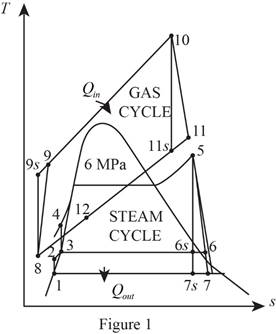
Refer Figure 1.
Consider the gas cycle (topping cycle) and their respective process states such as 8, 9,
At state 8:
The air enters the compressor at the temperature of
Refer Table A-17, “Ideal-gas properties of air”.
The enthalpy
Write the relative pressure and absolute pressure relation for the process 8-9-
Here, the relative pressure is
Write the formula for isentropic efficiency of compressor for the process 8-9-
Here, the enthalpy is
At state 10:
The air enters the turbine at the temperature of
Refer Table A-17, “Ideal-gas properties of air”.
The enthalpy
Write the relative pressure and absolute pressure relation for the process 10-11-
Write the formula for isentropic efficiency of gas turbine
At state 12: (heat exchanger)
The enthalpy
Refer Figure 1.
Consider the steam cycle (bottoming cycle) and their respective process states such as 1, 2, 3, 4, 5, 6,
At state 1: (Pump I inlet)
The water exits the condenser as a saturated liquid at the pressure of
Refer Table A-5, “Saturated water-Pressure table”.
The enthalpy
At state 2:
Write the formula for work done by the pump during process 1-2.
Here, the specific volume is
Write the formula for enthalpy
At state 3: (Pump II inlet)
The water exits the open feed water heater as a saturated liquid at the pressure of
Refer Table A-5, “Saturated water-Pressure table”.
The enthalpy
At state 4:
Write the formula for work done by the pump during process 3-4.
Here, the specific volume is
Write the formula for enthalpy
At state 5:
The steam enters the turbine as superheated vapour.
Refer Table A-6, “Superheated water”.
The enthalpy
At state
The steam expanded to the pressure of
The quality of water at state
The enthalpy at state
Here, the enthalpy is
Refer Table A-5, “Saturated water-Pressure table”.
Obtain the following properties corresponding to the pressure of
The isentropic efficiency of the steam turbine for the process 5-6-
At state
The steam enters the condenser at the pressure of
The quality of water at state
The enthalpy at state
Here, the subscript
Refer Table A-5, “Saturated water-Pressure table”.
Obtain the following properties corresponding to the pressure of
The isentropic efficiency of the steam turbine for the process 5-7-
Here, the subscript
Write the general energy rate balance equation.
Here, the rate of energy in is
Consider the heat exchanger operates on steady state. Hence, the rate of change in net energy of the system is zero.
The Equation (XVI) is reduced as follows for the heat exchanger.
Here, the mass flow rate of air is
Conclusion:
Substitute
Refer Table A-17, “Ideal-gas properties of air”.
The enthalpy
Substitute
Substitute
Refer Table A-17, “Ideal-gas properties of air”.
The enthalpy
Substitute
Substitute
Substitute
Substitute
Equation (VII).
Substitute
From Figure 1.
Substitute
Substitute
Equation (X).
Substitute
Substitute
Substitute
Equation (XIII).
Substitute
Substitute
Thus, the mass flow rate ratio of the air to the steam is
(b)
The required rate of heat input in the combustion chamber.
Answer to Problem 86P
The required rate of heat input in the combustion chamber is
Explanation of Solution
Refer Equation (XV).
Consider the open feed water heater operates on steady state. Hence, the rate of change in net energy of the system is zero.
Write the energy rate balance equation for open feed water heater.
Rewrite the Equation (XVII) in terms of mass fraction
Here, the mass fraction steam extracted from the turbine to the inlet mass of the boiler
Write the formula for work output of the steam turbine.
Write the formula for net work output of the steam cycle.
Write the formula for net work output of the gas cycle.
Write the formula for the net work output of the gas-steam cycle per unit mass of gas.
Write the formula for mass flow rate of air through the compressor.
Write the formula for rate of heat input to the combustion chamber.
Conclusion:
Substitute
Equation (XVIII).
Substitute
Substitute
Substitute
Substitute
Substitute
Substitute
Equation (XXIV).
Thus, the required rate of heat input in the combustion chamber is
(c)
The thermal efficiency of the combined cycle.
Answer to Problem 86P
The thermal efficiency of the combined cycle is
Explanation of Solution
Write the formula for thermal efficiency.
Conclusion:
Substitute
Thus, the thermal efficiency of the combined cycle is
Want to see more full solutions like this?
Chapter 10 Solutions
Thermodynamics: An Engineering Approach


- Consider a steam power plant operating on the ideal Rankine cycle. Steam enters the turbine at 3 MPa and 623 K and is condensed in the condenser at a pressure of 10 kPa. Determine (i) the thermal efficiency of this power plant, (ii) the thermal efficiency if steam is superheated to 873 K instead of 623 K, and (iii) the thermal efficiency if the boiler pressure is raised to 15 MPa while the turbine inlet temperature is maintained at 873 K.arrow_forwardA steam power plant operating on the intermediate steam Rankine cycle produces a net power of 160 MW. Water vapor enters the turbine at a pressure of 15 MPa and a temperature of 600 oC, and the condenser at a pressure of 15 kPa. The isentropic efficiency of the turbine is 85 percent and the isentropic efficiency of the pumps is 90 percent. In order to heat the feed water, some steam is separated from the turbine at a pressure of 0.6 MPa and sent to the open feedwater heater and exits the heater as a saturated liquid. Accordingly, fill in the blanks below. (Pump 1 inlet will be considered as saturated liquid.) a) The mass flow rate of the steam passing through the boiler is m5= ..... kg/s. b) The mass flow rate of the steam separated from the turbine to heat the feed water is m6= ...... kg/s. c) The heat entering the cycle is Qin = ...... kW. d) The heat released from the cycle is Qout = ...... kW. e) The power produced in the turbine is WTurbine= ...... kW. f) The power consumed in…arrow_forwardA steam power plant operates on an ideal reheat Rankine cycle between the pressure limits of 14 MPa and 10 kPa. The mass flow rate of steam through the cycle is 10 kg/s. Steam enters both stages of the turbine at 500°C. If the moisture content of the steam at the exit of the low-pressure turbine is not to exceed 12 percent, determine (a) the pressure at which reheating takes place, (b) the total rate of heat input in the boiler, and (c) the thermal efficiency of the cycle. Also, show the cycle on a T-s diagram with respect to saturation lines.arrow_forward
- Consider a steam power plant operating on the ideal Rankine cycle. Steam enters the turbine at 3 MPa and 350°C and is condensed in the condenser at a pressure of 10 kPa. Determine the thermal efficiency of this power plant, the thermal efficiency if steam is superheated to 600°C instead of 350°C, and the thermal efficiency if the boiler pressure is raised to 15 MPa while the turbine inlet temperature is maintained at 600°C. Draw the T-S diagram of each condition.arrow_forwardWhat components can be added to a simple open cycle gas turbine power plant in order to increase its efficiency? Given the gas turbine is powered with auto-diesel fuel.arrow_forwardIn a steam power plant that operates based on a Rankine cycle, the operating pressures of the steam generator and the condenser are 10,000 and 10 kPa, respectively. If the turbine inlet stream is saturated vapor and the condenser outlet flow is saturated liquid, determine the specific heat transfers in the steam generator and the condenser, the specific work involved in the turbine and the pump, and the thermal efficiency and the BWR of the cycle. Also, if the power plant produces 250 MW power, determine the mass flow rate of the cycle’s working fluid.arrow_forward
- NOTE: This is a multi-part question. Once an answer is submitted, you will be unable to return to this part. The gas-turbine cycle of a combined gas–steam power plant has a pressure ratio of 8. Air enters the compressor at 290 K and the turbine at 1400 K. The combustion gases leaving the gas turbine are used to heat the steam at 15 MPa to 450°C in a heat exchanger. The combustion gases leave the heat exchanger at 247°C. Steam expands in a high-pressure turbine to a pressure of 3 MPa and is reheated in the combustion chamber to 500°C before it expands in a low-pressure turbine to 10 kPa. The mass flow rate of steam is 12 kg/s. Assume isentropic efficiencies of 100 percent for the pump, 85 percent for the compressor, and 90 percent for the gas and steam turbines. A.) Determine the mass flow rate of air in the gas-turbine cycle. Use steam tables and the table containing the ideal-gas properties of air. The mass flow rate of air in the gas-turbine cycle is ___?___kg/s…arrow_forwardThermodynamics 2 Consider a steam power plant that operates on a reheat Rankine cycle and has a net power output of 91 MW. Steam enters the high-pressure turbine at 10 MPa and 500 C and the low-pressure turbine at 1 MPa and 500 C. Steam leaves the condenser as a saturated liquid at a pressure of 10 kPa. The isentropic efficiency of the turbine is 95 percent, and that of the pump is 90 percent. The required power input in the pump in MW.arrow_forwardConsider a steam power plant that operates on the ideal reheat Rankine cycle. The plant maintains the boiler at 5400 kPa, the reheat section 1100 kPa, and the condenser at 10 kPa. The mixture quality at the exit of both turbines is 94 %. Determine the following values. (1) The specific enthalpy at the exit of the high-pressure turbine. (2) The specific entropy at the exit of the high-pressure turbine. (3) The temperature at the inlet of the high-pressure turbine. (4) The temperature at the inlet of the low-pressure turbine. (5) The thermal efficiency of the cycle.arrow_forward
- The second steam power plant operates on a regenerative Rankine cycle, where water is used as the working fluid. Steam enters the turbine at 8 MPa and 450 ºC. After isentropic expansion in the first stage of the turbine, steam is extracted at an intermediate pressure of 0.75 MPa and passed to a closed feedwater heater. The feedwater leaves the heater at 8 MPa and a temperature equal to the saturation temperature at 0.75 MPa. The saturated liquid condensate from the feedwater heater leaves at 0.75 MPa and is pumped into the feedwater line. The condenser pressure is 7.5 kPa. The net power output from the cycle is 100 MW Task 41. Draw the TS diagram for this system and clearly label all the states2. Find the rate of heat transfer to the working fluid passing through the steam generator.3. Determine the thermal efficiency of the cycle.4. Explain how the turbine work output, heat supplied, heat rejected and moisture content at turbine exit change when regeneration is added to a simple ideal…arrow_forwardConsider a reheat-regenerative vapor power cycle with two feedwater heaters, a closed feedwater heater and an open feedwater heater. Steam enters the first turbine at 8000 kPa and 480oC and expands to 700 kPa. The steam is reheated to 440oC before entering the second turbine, where it expands to the condenser pressure of 8 kPa. Steam is extracted from the first turbine at 2000 kPa and fed to the closed feedwater heater. The feedwater leaves the closed heater at 205oC and 8000 kPa and enters the boiler to complete the cycle. The condensate from the closed feedwater heater is throttled into the open feedwater heater. Steam extracted from the second turbine at 300 kPa is also fed into the open feedwater heater, which operates at 300 kPa. The stream exiting the open feedwater heater is saturated liquid at 300 kPa. The net power output of the cycle is 100 MW. If the working fluid experiences no irreversibilities as it passes through the turbines and pumps, determine: (a) mass flowrate of…arrow_forward1. What is the Isentropic Work of the Steam using the Ideal Rankine Cycle when the system is set at 400 kPaa Boiler Pressure and 105 kPaa Condenser Pressure when the system is generating power at 9,500 seconds? 2. With the Turbine work output, what is the Isentropic efficiency of the Turbine from the above settings?arrow_forward
 Elements Of ElectromagneticsMechanical EngineeringISBN:9780190698614Author:Sadiku, Matthew N. O.Publisher:Oxford University Press
 Mechanics of Materials (10th Edition)Mechanical EngineeringISBN:9780134319650Author:Russell C. HibbelerPublisher:PEARSON
 Thermodynamics: An Engineering ApproachMechanical EngineeringISBN:9781259822674Author:Yunus A. Cengel Dr., Michael A. BolesPublisher:McGraw-Hill Education
 Control Systems EngineeringMechanical EngineeringISBN:9781118170519Author:Norman S. NisePublisher:WILEY
 Mechanics of Materials (MindTap Course List)Mechanical EngineeringISBN:9781337093347Author:Barry J. Goodno, James M. GerePublisher:Cengage Learning
 Engineering Mechanics: StaticsMechanical EngineeringISBN:9781118807330Author:James L. Meriam, L. G. Kraige, J. N. BoltonPublisher:WILEY