
Videos
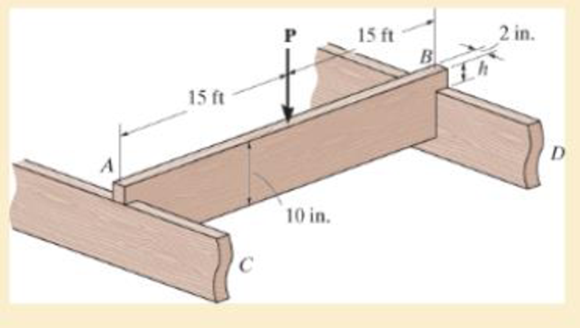
The simply supported joist is used in the construction of a floor for a building. In order to keep the floor low with respect to the sill beams C and D, the ends of the joist are notched as shown. If the allowable shear stress is τallow = 350 psi and the allowable bending stress is σallow = 1700 psi, determine the smallest height h so that the beam will support a load of P = 600 lb. Also, will the entire joist safely support the load? Neglect the stress concentration at the notch.
Want to see the full answer?
Check out a sample textbook solution
Chapter 11 Solutions
Mechanics Of Materials, Si Edition
Additional Engineering Textbook Solutions
Engineering Mechanics: Dynamics (14th Edition)
Automotive Technology: Principles, Diagnosis, And Service (6th Edition) (halderman Automotive Series)
EBK FUNDAMENTALS OF THERMODYNAMICS, ENH
Thinking Like an Engineer: An Active Learning Approach (3rd Edition)
Fluid Mechanics: Fundamentals and Applications
Fluid Mechanics Fundamentals And Applications


- The eye hook has the dimensions shown. If it supports a cable loading of 800 lb, determine the maximum normal stress at section a–a and sketch the stress distribution acting over the cross section. Use the curved-beam formula to calculate the bending stress.arrow_forward1–1. The shaft is supported by a smooth thrust bearing at B and a journal bearing at C. Determine the resultant internal loadings acting on the cross section at E. Problem 1–1arrow_forwardIf the internal moment acting on the cross-section is 800 N.m, determine the maximum tensile and compressive bending stresses acting in the beam. Sketch the stress-distribution acting on the cross-section.arrow_forward
- The handle of the press is subjected to a force of 20 lb. Due to internal gearing, this causes the block to be subjected to a compressive force of 80 lb. Determine the normal-stress acting in the frame at points along the outside flanges A and B. Use the curved-beam formula to calculate the bending stress.arrow_forwardbeam is supported by a roller and a hinge at its extremities. The 2 kN/m is loaded entirely on its 4 m length while 5 kN concentrated load is positioned 2 m from the left end of this beam. If the beam is 80 mm wide, determine the minimum height of the beam if the flexural stress is not to exceed 10 MPa.arrow_forwardThe singular force F will be applied to the beam with a hollow rectangular cross section. Accordingly, the location and value of the maximum normal stress that will occur in the whole beam is given correctly in the following? F =400 N, L1 = 3m, L2 = 2m, h1=48mm, h2 =72mm, b1=10mm, b2=20mmarrow_forward
- The overhang beam is constructed using two 2-in. by 4-in. pieces of wood braced as shown. If the allowable bending stress is sallow = 600 psi, determine the largest load P that can be applied. Also, determine the maximum spacing of nails, s, along the beam section AC if each nail can resist a shear force of 800 lb. Assume the beam is pin connected at A, B, and D. Neglect the axial force developed in the beam along DA.arrow_forwardIf the beam is made of material having an allowable tensile and compressive stress of (sallow)t = 125 MPa and (sallow)c = 150 MPa, respectively, determine the maximum moment M that can be applied to the beam.arrow_forwardThe axle of the freight train is subjected to loadings as shown below. The diameter of the axle is 137.5 mm. If it is supported by two journal bearings at C and D, determine the maximum bending Stress. Include a FBD, SFD and BMD using either the section or graphical method. Draw a cross-section of the shaft and indicate the points of maximum tension and compression.arrow_forward
- The member consists of two plastic channel strips 0.5 in. thick, glued together at A and B. If the glue can support an allowable shear stress of tallow= 600 psi, determine the maximum intensity w0 of the triangular distributed loading that can be applied to the member based on the strength of the glue.arrow_forwardDetermine the stress distribution of the beam in cross section A-B when its dimensions are a = 4.0 m, b = 0.5 m, c = 124 mm, and d = 100 mm. The magnitude of the force P is 35 kN. How much are in cross section A-B normal force shear force bending moment normal stress at the top of the beam normal stress at the lower surface of the beam maximum shear stress shear stress at y = 62 mm from the lower levelarrow_forward(d) How far is the maximum compressive bending stress located from support A? (Consider x=0 at support A) (e) Calculate the maximum shear stress. (Express the stress in Pa or MPa) and determine the location of maximum shear stress with respect to neutral axis. (f) How far is the maximum shear stress located located from support A? (Consider x=0 at support A)arrow_forward
 Elements Of ElectromagneticsMechanical EngineeringISBN:9780190698614Author:Sadiku, Matthew N. O.Publisher:Oxford University Press
 Mechanics of Materials (10th Edition)Mechanical EngineeringISBN:9780134319650Author:Russell C. HibbelerPublisher:PEARSON
 Thermodynamics: An Engineering ApproachMechanical EngineeringISBN:9781259822674Author:Yunus A. Cengel Dr., Michael A. BolesPublisher:McGraw-Hill Education
 Control Systems EngineeringMechanical EngineeringISBN:9781118170519Author:Norman S. NisePublisher:WILEY
 Mechanics of Materials (MindTap Course List)Mechanical EngineeringISBN:9781337093347Author:Barry J. Goodno, James M. GerePublisher:Cengage Learning
 Engineering Mechanics: StaticsMechanical EngineeringISBN:9781118807330Author:James L. Meriam, L. G. Kraige, J. N. BoltonPublisher:WILEY