
Concept explainers
Videos
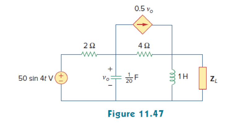
For the circuit in Fig. 11.47, find the value of ZL that will receive the maximum power from the circuit. Then calculate the power delivered to the load ZL.
Find the value of the load impedance
Answer to Problem 16P
The value of load impedance
Explanation of Solution
Given data:
Refer to Figure 11.47 in the textbook.
The inductance
The capacitance C is
The source voltage is
Formula used:
Write the general expression for the instantaneous voltage.
Write the expression to find the maximum average power.
Here,
Write the expression for
Calculation:
On comparing equation (1) and (2), the angular frequency is,
Write the expression for the reactance of the inductance.
Substitute
Write the expression for the reactance of the capacitance.
Substitute
Refer to Figure 11.47 in the textbook.
To find the Thevenin equivalent the given Figure is modified as shown in Figure 1.
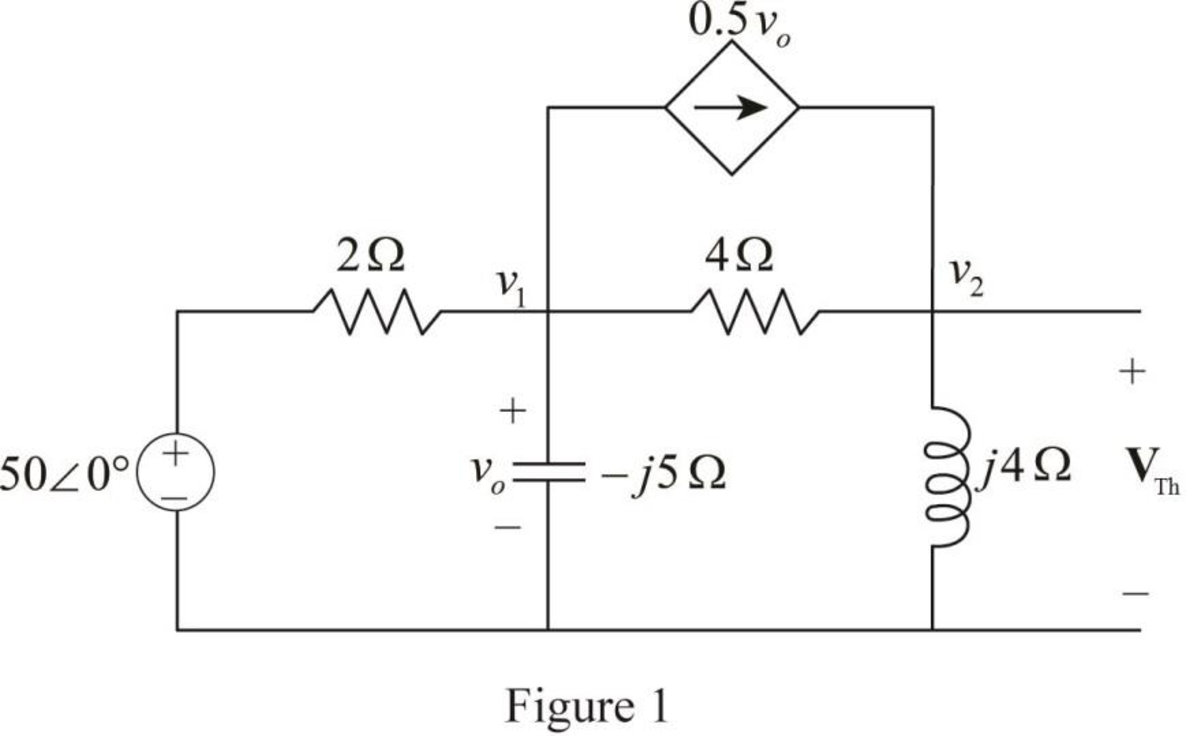
In Figure 1, apply Kirchhoff’s currrent law at node voltage
Rearrange the equation as follows,
In Figure 1, apply Kirchhoff’s currrent law at node voltage
Rearrange the equation as follows,
Substitute equation (6) in equation (5).
Rearrange the equation as follows,
The voltage voltage
Convert the equation from rectangular to polar form.
The Thevenin voltage is,
In Figure 1, to calculate the Thevenin impedance
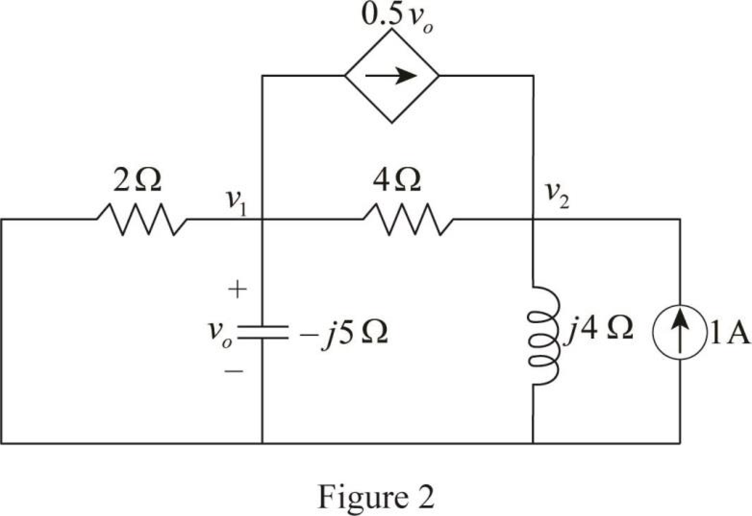
In Figure 2, apply Kirchhoff’current law at node voltage
Rearrange the equation as follows,
In Figure 2, apply Kirchhoff’current law at node voltage
Rearrange the equation as follows,
Substitute equation (7) in equation (8).
Rearrange the equation as follows,
Convert the equation from rectangular to polar form.
The Thevenin impedance
Substitute
Convert the equation from polar to rectangular form.
For maximum average power transfer, the load impedance
Convert the equation from rectangular to polar form.
On comparing the equation (9) with equation (4).
Substitute
Conclusion:
Thus, the value of load impedance
Want to see more full solutions like this?
Chapter 11 Solutions
Fundamentals of Electric Circuits


- A load of 500 kVA operates on 1100 V, 50 Hz mains with power factor of 0.6 lagging. It is required to improve the power factor to 0.95 lagging by using the star connected capacitor bank. Assuming that the load KVA remains constant, suggest the rating of the capacitors.arrow_forwarda power station has a connected load of 48MW. the energy generated for the year is 61500MWh. if the station has a load factor of 35%. solve the demand factor of the station. Subject: Distribution System and Substation Designarrow_forward. A power station has a connected load of 48 MW. The energy generated for the year is 61,500 MWh. If the station has a load factor of 35%, solve the demand factor of the station. Answer: 0.4179 or 41.79% Subject: Distribution System and Substation Designarrow_forward
- The two wattmeters in Fig. 11.20 can be used to compute the total reactive power of the load. Prove this statement by showing that 3(W2−W1)=3VLIL sinθϕ.arrow_forwardA series generator delivers a power of 6.25kW and a load resistance of25Ω. If RA=0.05Ω and RS=0.025Ω, calculate the generated emf.arrow_forwardIf an AC motor with impedance ZL= 4.2+j3.6 ohm is supplied by 220 vrm, 60HZ source. Find the p.f, pav, and Q.arrow_forward
- When drawing three-phase inductive 250 kW from the 440 V transmission line, the power coefficient is 0.707. When a three-phase parallel 60 kVAR capacitor group is connected to this load, find the current drawn from the line and the power coefficient?arrow_forwardPower factor is 0.707 when three-phase inductive 250 kW power is drawn from 440 V transmission line. When a three-phase parallel 60 kVAR capacitor group is connected to this load, find the current and power factor drawn from the line.arrow_forwardGiven a tee connected system with power factor of 80 percent and true power of 2,500 kW. Calculate the reactive power.arrow_forward
- A power station has a maximum demand of 40 MW. The total load connected to the station is 100 MW. If the average demand at the station is 25 MW, find (1) the load factor (2) the demand factor and (3) the connected load factorarrow_forwardProblem 11.34. At full load, a commercially available 106 hp, three-phase induction motor operates at an efficiency of 96% and a power factor of 0.87 lag. The motor is supplied from a three-phase outlet with a line-voltage rating of 208 V. 1. What is the magnitude of the line current in Ampere drawn from the 208 V outlet? (1 hp = 746 W). 2. Calculate the reactive power in kVAR supplied to the motor.arrow_forwardThe impedance of an electrical circuit is (30 − j50) ohms. Determine (a) the resistance, (b) the capacitance, (c) the modulus of the impedance, and (d) the current flowing and its phase angle, when the circuit is connected to a 240V, 50 Hz supply.arrow_forward
 Introductory Circuit Analysis (13th Edition)Electrical EngineeringISBN:9780133923605Author:Robert L. BoylestadPublisher:PEARSON
 Delmar's Standard Textbook Of ElectricityElectrical EngineeringISBN:9781337900348Author:Stephen L. HermanPublisher:Cengage Learning
 Programmable Logic ControllersElectrical EngineeringISBN:9780073373843Author:Frank D. PetruzellaPublisher:McGraw-Hill Education
 Fundamentals of Electric CircuitsElectrical EngineeringISBN:9780078028229Author:Charles K Alexander, Matthew SadikuPublisher:McGraw-Hill Education
 Electric Circuits. (11th Edition)Electrical EngineeringISBN:9780134746968Author:James W. Nilsson, Susan RiedelPublisher:PEARSON
 Engineering ElectromagneticsElectrical EngineeringISBN:9780078028151Author:Hayt, William H. (william Hart), Jr, BUCK, John A.Publisher:Mcgraw-hill Education,