
MECHANICAL ENGINEERING DES.(LL)-W/CNCT
15th Edition
ISBN: 9781260531374
Author: BUDYNAS
Publisher: MCG
expand_more
expand_more
format_list_bulleted
Concept explainers
Videos
Textbook Question
Chapter 11, Problem 16P
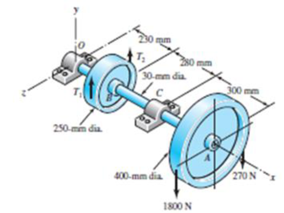
A countershaft carrying two V-belt pulleys is shown in the figure. Pulley A receives power from a motor through a belt with the belt tensions shown. The power is transmitted through the shaft and delivered to the belt on pulley B. Assume the belt tension on the loose side at B is 15 percent of the tension on the tight side.
11-14* to 11-17* For the problem specified in the table, build upon the results of the original problem to obtain a Basic Load Rating for a ball bearing at C with a 95 percent reliability, assuming distribution data from manufacturer 2 in Table 11-6. The shaft rotates at 1200 rev/min, and the desired bearing life is 15 kh. Use an application factor of 1.2.
| Problem Number | Original Problem, Page Number |
| 11-14* | 3-68, 151 |
| 11-15* | 3-69, 151 |
| 11-16* | 3-70, 151 |
| 11-17* | 3-71, 151 |
Problem 3-69*
Expert Solution & Answer
Want to see the full answer?
Check out a sample textbook solution
Students have asked these similar questions
A countershaft carrying two V-belt pulleys is shown in the figure.
Pulley A receives power from a motor through a belt with the belt tensions shown. The power is transmitted through the shaft and delivered to the belt on pulley B.
Assume the belt tension on the loose side at B is 15 percent of the tension on the tight side.
A belt drive is used to transmit power from an electric motor to a compressor for a refrigerated truck. The compressor must still operate when the truck is parked and the engine is not running. The 50-hp electric motor is rated at 150+X rpm (where value of X = 50), and the motor sheave diameter is 5+d1 in. (where value of d1 = 5). The compressor sheave has 8+d2 in (where value of d2 = 5) diameter. The center distance of the drive is 15 in. Determine the appropriate industrial V belt size, the length of belt, operating speed of compressor and belt speed.
The machine is designed to be powered by a 100 HP electric motor at a speed of 1500 rpm, with standard D-120 V-belts. The pitch diameter of the smaller sheave is 101.6 mm and the bigger sheave is 406.4 mm. Service factor is 1.25. Use length of D-120 V-belt equal to 123.3 inches. Determine the center distance between sheaves in mm; the arc of contact in deg; and the design in HP.
Chapter 11 Solutions
MECHANICAL ENGINEERING DES.(LL)-W/CNCT
Ch. 11 - Manufacturer Rating Life, Revolutions Weibull...Ch. 11 - Manufacturer Rating Life, Revolutions Weibull...Ch. 11 - Manufacturer Rating Life, Revolutions Weibull...Ch. 11 - Problems 112 and 113 raise the question of the...Ch. 11 - Prob. 5PCh. 11 - Manufacturer Rating Life, Revolutions Weibull...Ch. 11 - Two ball bearings from different manufacturers are...Ch. 11 - 11-8 to 11-13 For the bearing application...Ch. 11 - 11-8 to 11-13 For the bearing application...Ch. 11 - 11-8 to 11-13 For the bearing application...
Ch. 11 - 11-8 to 11-13 For the bearing application...Ch. 11 - 11-8 to 11-13 For the bearing application...Ch. 11 - 11-8 to 11-13 For the bearing application...Ch. 11 - A countershaft carrying two V-belt pulleys is...Ch. 11 - A countershaft carrying two V-belt pulleys is...Ch. 11 - A countershaft carrying two V-belt pulleys is...Ch. 11 - A countershaft carrying two V-belt pulleys is...Ch. 11 - For the shaft application defined in Prob. 3-77,...Ch. 11 - For the shaft application defined in Prob. 3-79,...Ch. 11 - An 02-series single-row deep-groove ball bearing...Ch. 11 - An 02-series single-row deep-groove ball bearing...Ch. 11 - 11-22 to 11-26 An 02-series single-row deep-groove...Ch. 11 - 1122 to 1126 An 02-series single-row deep-groove...Ch. 11 - 1122 to 1126 An 02-series single-row deep-groove...Ch. 11 - 1122 to 1126 An 02-series single-row deep-groove...Ch. 11 - 1122 to 1126 An 02-series single-row deep-groove...Ch. 11 - The shaft shown in the figure is proposed as a...Ch. 11 - Repeat the requirements of Prob. 11-27 for the...Ch. 11 - The shaft shown in the figure is proposed as a...Ch. 11 - Repeat the requirements of Prob. 11-29 for the...Ch. 11 - Shown in the figure is a gear-driven squeeze roll...Ch. 11 - The figure shown is a geared countershaft with an...Ch. 11 - The figure is a schematic drawing of a...Ch. 11 - A gear-reduction unit uses the countershaft...Ch. 11 - The worm shaft shown in part a of the figure...Ch. 11 - In bearings tested at 2000 rev/min with a steady...Ch. 11 - A 16-tooth pinion drives the double-reduction...Ch. 11 - Estimate the remaining life in revolutions of an...Ch. 11 - The same 02-30 angular-contact ball bearing as in...Ch. 11 - A countershaft is supported by two tapered roller...Ch. 11 - For the shaft application defined in Prob. 3-74,...Ch. 11 - For the shaft application defined in Prob. 3-76,...Ch. 11 - Prob. 43PCh. 11 - The gear-reduction unit shown has a gear that is...
Knowledge Booster


Learn more about
Need a deep-dive on the concept behind this application? Look no further. Learn more about this topic, mechanical-engineering and related others by exploring similar questions and additional content below.Similar questions
- Repeat Problem 11.2-14 using L = 12 ft, ß = 0.25 kips/in., ßRl= 1.5ßL2, and ßR2= 2 ßR1.arrow_forwardRepeat Problem 11.2-3 assuming that R= 10 kN · m/rad and L = 2 m.arrow_forwardA hand cranking lever, as shown in Figure 6 below, is used to start a truck engine byapplying a force F = 400 N. The material of the cranking lever has a yield strength = 320 MPa;Ultimate tensile strength = 500 MPa; Young’s modulus = 205 GPa; Modulus of rigidity = 84 GPaand poisson’s ratio = 0.3. Assuming factor of safety to be 4 based on yield strength, design thediameter of the lever at section X-X near the guide bush using: a) Maximum distortion energytheory; and b) Maximum shear stress theory.arrow_forward
- A belt conveyor transports 18 tonnes per hr at 20°. Determine the speed reducer power factor to lift the load vertically up sufficient to give 33.5 m horizontal center-to-center pulley distance. 1750-rpm motor, plain chain drive to helical gear speed reducer. Belt speed, 61 m/min. Discharge over tail pulley. No tripper.arrow_forwardA link has a load factor of 0.80 the surface factor of 0.80. The surface factor is 0.92 and the endurance strength is 28000 psi. Compute the alternating stress of the link if it is subjected to a reversing load. Assume a factor of safety of 3. A. 8150 B. 10920 C. 9,333 D. 7260 Please solve the Problem elaborately and Refer Machine Elements and Stresses Equations from the figures or use other shortcut Methods you have or you may Solve both or in more different methods the better ?. Your solution will be use as reference for my Future Board Exam preparation/review/study. Thank you so much dear your work will be appreciated much and rated excellently.arrow_forwardThe figure 1 shows a pulley assembly that consists of a shaft supported by two bearings and driven by a motor on the righthand side (not shown in the figure). The shaft diameter is 100mm. The pulley consists of two disks, each disk is 15 mm thick and has an outer diameter of 620mm, that are connected by means of a cylindrical shell. The length of the shell is 500mm, the outer diameter of the shell is 600mm, and the thickness of the shell is 15mm. The pulley drives a belt that places a uniformly distributed load on the shell (of 100000N) as shown in the diagram. The belt lifts a load that applies a torque of 6000Nm to the pulley. The shell and the plates are connected. A 6mm fillet should be applied to all the 90 degree corners between the shaft and the plates and between the shell and the plates. The highest stress in the systemarrow_forward
- The figure 1 shows a pulley assembly that consists of a shaft supported by two bearings and driven by a motor on the righthand side (not shown in the figure). The shaft diameter is 100mm. The pulley consists of two disks, each disk is 15 mm thick and has an outer diameter of 620mm, that are connected by means of a cylindrical shell. The length of the shell is 500mm, the outer diameter of the shell is 600mm, and the thickness of the shell is 15mm. The pulley drives a belt that places a uniformly distributed load on the shell (of 100000N) as shown in the diagram. The belt lifts a load that applies a torque of 6000Nm to the pulley. The shell and the plates are connected. A 6mm fillet should be applied to all the 90 degree corners between the shaft and the plates and between the shell and the plates. Apply the boundary conditions and the forces and torques to the system and determine the following: Calculate the highest Principal stresses in the system ?arrow_forwardThe worm shaft shown in the figure transmits 1-kW at 500 rev/min. A static forceanalysis results are also shown in the figure. Bearing A is to be an angular-contact ballbearing mounted to take the 2.75 kN thrust load. The bearing at B is to take only theradial load, so a straight roller bearing will be employed. Use an application factor of1.2, a desired life of 25 kh, and a combined reliability goal of 0.99. (a)Specify each bearing by giving all required charecteristics. (b) Determine the radial and thrust components of loads on each bearing. (c) Make a design assessment for each bearing and of the system.arrow_forwardA helical compression spring has a scale of 500 lb/in., an outside diameter of 2.75 in, a free length of 8 inches and with squared and ground ends. The load is 1,000 lbs and the working stress on the wire material is 65000 psi. If the Wahl factor of 1.25 is to be used, calculate the following: A. The standard wire diameter B. The number of active coil if G = 10 800 000 psi C. The solid height D. The stress at solid heightarrow_forward
- A mechanism used in a punchingmachinery consists of a tension spring assembled with a preload of 30 N. The wire diameter of spring is 2 mm with a spring index of 7. The spring has 10active coils. The spring wire is hard drawn and oil tempered having the following material properties:Design shear stress = 780 MPa Modulus of rigidity = 80 kN/mm2Identify (a) the initial torsional shear stress in the wire, (b) the spring rate, and (c) the force to cause the body of the spring to reach its yield strength.arrow_forwardA plate clutch has 3 discs on the driving shaft and 2 discs on the driven shaft, providing four pairs of contact surfaces. The outside diameter of the contact surfaces is 240 mm and inside diameter 120 mm. Assuming uniform pressure and coeff. Of friction is 0.3. Find the total spring load pressing the plates together to transmit 23kw power at 1475 revolution per minute. If there 6 springs each of stiffness 13 kN/m and each of the contact surfaces has worn away by 1.25 mm. find the maximum power that can be transmitted assuming uniform wear. A plate clutch has 3 discs on the driving shaft and 2 discs on the driven shaft, providing four pairs of contact surfaces. The outside diameter of the contact surfaces is 240 mm and inside diameter 120 mm. Assuming uniform pressure and coeff. Of friction is 0.3. Find the total spring load pressing the plates together to transmit 23kw power at 1475 revolution per minute. If there 6 springs each of stiffness 13 kN/m and each of the contact surfaces…arrow_forwardIn the design in the figure, a force of Fn=45992 N acts in the vertical plane on a machine element with a diameter of D=200 mm on the shaft resting on the A and B bearings. If the angle made by this force with the horizontal is b=40o, find the life of the 6210 coded Deep Ball bearing to be used in the B bearing, in hours. Number of revolutions = 30 rpm. 1-) The diameter of the machine element on which the force acts will be taken into account in the calculation of bearing forces (That is, it will be assumed that the Fn force AFFECTS THE GROUND shown in the figure, NOT the axis of the shaft). 2-) Pi number will be taken as 3.14.arrow_forward
arrow_back_ios
SEE MORE QUESTIONS
arrow_forward_ios
Recommended textbooks for you
 Mechanics of Materials (MindTap Course List)Mechanical EngineeringISBN:9781337093347Author:Barry J. Goodno, James M. GerePublisher:Cengage Learning
Mechanics of Materials (MindTap Course List)
Mechanical Engineering
ISBN:9781337093347
Author:Barry J. Goodno, James M. Gere
Publisher:Cengage Learning
Engineering Basics - Statics & Forces in Equilibrium; Author: Solid Solutions - Professional Design Solutions;https://www.youtube.com/watch?v=dQBvQ2hJZFg;License: Standard YouTube License, CC-BY