
Introductory Circuit Analysis
13th Edition
ISBN: 9780133923919
Author: Boylestad, Robert L.
Publisher: Pearson Education
expand_more
expand_more
format_list_bulleted
Videos
Textbook Question
Chapter 11, Problem 30P
The switch in Fig. 11.97 has been closed for a long time. It is then opened at
a. Write the mathematical expression for the current iL and the voltage vL after the switch is opened.
b. Sketch the waveform of iL and vL from initial value to the steady-state leve.
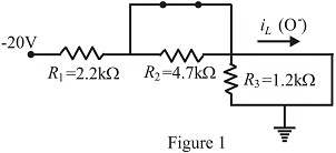
Fig. 11.97
Expert Solution & Answer
Want to see the full answer?
Check out a sample textbook solution
Students have asked these similar questions
A motor with 1mH of inductance and an unknown internal resistance is connected to a 100V RMS 10kHz source. The power factor has been corrected by adding a 247nF capacitor in parallel with the motor. Calculate the value of the internal resistance.
A relay has a 500-turn coil that draws 50 mA rms when a 60-Hz voltage of 24 V rms is applied. Assume that the resistance of the coil is negligible. Determine the peak flux linking the coil, the reluctance of the core, and the inductance of the coil.
What is the equation of a 25 cycle current wave having rms value of 45 amp?
a. 31.8198 sin 157.08 t
b. 45 sin 157.08 t
c. 63.6393 sin 157.08 t
d. 90 sin 157.08 t
Chapter 11 Solutions
Introductory Circuit Analysis
Ch. 11 - For the electromagnet in Fig. 11.75: a. Find the...Ch. 11 - For the inductor in Fig. 11.76, find the...Ch. 11 - a. Repeat Problem 2 with a ferromagnetic core with...Ch. 11 - For the inductor in Fig. 11.77, find the...Ch. 11 - An air-core inductor has a total inductance of 4.7...Ch. 11 - What are the inductance and the range of expected...Ch. 11 - If the flux linking a coil of 50 turns changes at...Ch. 11 - Determine the rate of change of flux linking a...Ch. 11 - How many turns does a coil have if 42 mV are...Ch. 11 - Find the voltage induced across a coil of 22 mH if...
Ch. 11 - For the circuit of Fig. 11.78 composed of standard...Ch. 11 - For the circuit in Fig. 11.79 composed of standard...Ch. 11 - For the network of Fig. 11.80. a. Write the...Ch. 11 - Give a supply of 18 V, use standard values to...Ch. 11 - For the circuit in Fig. 11.82: a. Write the...Ch. 11 - In this problem, the effect of reversing the...Ch. 11 - For the network of Fig. 11.84: a. Find the...Ch. 11 - Prob. 18PCh. 11 - Prob. 19PCh. 11 - Prob. 20PCh. 11 - For the network in Fig. 11.88: a. Determine the...Ch. 11 - For the network in Fig. 11.89: a. Write the...Ch. 11 - Prob. 23PCh. 11 - For Fig. 11.91: a. Determine the mathematical...Ch. 11 - For Fig. 11.92: a. Determine the mathematical...Ch. 11 - For the network in Fig. 11.93, the switch is...Ch. 11 - The switch in Fig. 11.94 has been open for a long...Ch. 11 - Prob. 28PCh. 11 - The switch for the network in Fig. 11.96 has been...Ch. 11 - The switch in Fig. 11.97 has been closed for a...Ch. 11 - Given iL=100mA(1e-t/20ms) a. Determine iLatt=1ms....Ch. 11 - a. If the measured current for an inductor during...Ch. 11 - The network in Fig. 11.98 employs a DMM with an...Ch. 11 - Find the waveform for the voltage induced across a...Ch. 11 - Find the waveform for the voltage induced across a...Ch. 11 - Prob. 36PCh. 11 - Find the total inductance of the circuit of Fig....Ch. 11 - Find the total inductance for the network of Fig....Ch. 11 - Reduce the network in Fig. 11.104 to the fewest...Ch. 11 - Reduce the network in Fig. 11.105 to the fewest...Ch. 11 - Reduce the network of Fig. 11.106 to the fewest...Ch. 11 - For the network in Fig. 11.107: a. Write the...Ch. 11 - For the network in Fig. 11.108: a. Write the...Ch. 11 - For the network in Fig. 11.109. a. Find the...Ch. 11 - Find the steady-state currents I1 and I2 for the...Ch. 11 - Find the steady-state currents and voltages for...Ch. 11 - Find the steady-state currents and voltages for...Ch. 11 - Find the indicated steady-state currents and...Ch. 11 - Prob. 49PCh. 11 - Using PSpice or Multisim, verify the results of...Ch. 11 - Using the PSpice or Multisim, find the solution to...Ch. 11 - Using PSpice or Multisim, find the solution to...Ch. 11 - Using PSpice or Multisim, verify the results of...
Knowledge Booster


Learn more about
Need a deep-dive on the concept behind this application? Look no further. Learn more about this topic, electrical-engineering and related others by exploring similar questions and additional content below.Similar questions
- A 70-Vac source has the following waveform. Determine:a. equation of the waveform (in time domain)b. the instantaneous voltage when t = 120 msc. the angle (1st occurrence) after t = 0 when the voltage is +80 Vd. the time (2nd occurrence) after t = 0 when the voltage is –10 Varrow_forwardThe voltage applied to a coil having R-2002 ohm, L-638 mH is represented by e=20 sin 100 ? t. Find a corresponding expression for the current and calculate the average value of the power taken by the coil.arrow_forward44. The equation for 60 cycles current sine wave having RMS value 30 amperes, will be __ A. 42.4 sin120pi t Amp B. 30 sin 120t AmpC. 30 sin60t AmpD. 42.4 sin 60pi t Amparrow_forward
- The self inductance of a coil of 500 turns is 0.25 H. If 60% of the flux is linked with second coil of 10,000 turns, then find the mutual inductance of the two coils.arrow_forward1. With a neat sketch briefly explain how an alternating voltage is produced when a coil is rotated in a magneticfield. 2. Derive expressions for average value and RMS value of a sinusoidally varying AC voltage 3. A circuit having a resistance of 12Ω, an inductance of 0.15 H and a capacitance of 100μf in series is connectedacross a 100V, 50Hz supply. Calculate the impedance, current, the phase difference between the current andsupply voltage. 4. Two circuits with impedances of Z1 = 10 + j15Ω and Z2 = 6 – j8Ω are connected in parallel. If the supply current is 20A, what is the power dissipated in each branch?arrow_forwardFor the circuit in fig .11.82 A. Write the mathematical expressions for the current IL and the voltage Vl following the closing of the switch. B. Sketch the waveform of iL and VL for the entire period from initial value to steady-state level.arrow_forward
- Understand ac power concepts, their relationships to one another, and how to calculate them in a circuit The periodic triangular current shown , has a peak value of 180 mA. Find the average power that this current delivers to a 5 kΩ resistor.arrow_forwardA sawmill uses a 15-hp electric motor operating at 480 V rms. Its power factor is 0.82. When a power-factor-correcting capacitor is added to the system, the power factor increases to 0.95. Find the rms current in the wires supplying the motor a) before and b) after the power factor increase.arrow_forwardTwo electric devices A and B are connected in parallel, and the rms current in A is 15 amp. If the current in B lags behind A by pi/3 radians and the line current is 23.4 amp, determine the current in B.arrow_forward
- In the circuit below, if the inductance L is large enough to operate in continuous current mode. a) Draw the waveform of the output voltage and mains current for the 45 degree trigger angle when the switch S is in transmission. b) Average value of output DA voltage VDC1 when switch S is open, output DA when switch S is closed (in transmission) If the average value of the voltage is VDC2, calculate the value of VDC1 / VDC2. Lesson: power electronics please quickarrow_forwardThe voltage v = 201 sin(100t+50°) V is connected acroos a 110-µF capacitor. Determine the current (RMS) in polar form. Write the magnitude only in four decimal places.arrow_forwardA resistor whose resistance is 50Ω is traversed by an alternating current that obeys the function I (t) = 8√2 sin (120πt) determinea) the rms value of the current and the rms value of the electrical potential difference.b) a power dissipated by the resistorarrow_forward
arrow_back_ios
SEE MORE QUESTIONS
arrow_forward_ios
Recommended textbooks for you
 Introductory Circuit Analysis (13th Edition)Electrical EngineeringISBN:9780133923605Author:Robert L. BoylestadPublisher:PEARSON
 Delmar's Standard Textbook Of ElectricityElectrical EngineeringISBN:9781337900348Author:Stephen L. HermanPublisher:Cengage Learning
 Programmable Logic ControllersElectrical EngineeringISBN:9780073373843Author:Frank D. PetruzellaPublisher:McGraw-Hill Education
 Fundamentals of Electric CircuitsElectrical EngineeringISBN:9780078028229Author:Charles K Alexander, Matthew SadikuPublisher:McGraw-Hill Education
 Electric Circuits. (11th Edition)Electrical EngineeringISBN:9780134746968Author:James W. Nilsson, Susan RiedelPublisher:PEARSON
 Engineering ElectromagneticsElectrical EngineeringISBN:9780078028151Author:Hayt, William H. (william Hart), Jr, BUCK, John A.Publisher:Mcgraw-hill Education,
Introductory Circuit Analysis (13th Edition)
Electrical Engineering
ISBN:9780133923605
Author:Robert L. Boylestad
Publisher:PEARSON
Delmar's Standard Textbook Of Electricity
Electrical Engineering
ISBN:9781337900348
Author:Stephen L. Herman
Publisher:Cengage Learning
Programmable Logic Controllers
Electrical Engineering
ISBN:9780073373843
Author:Frank D. Petruzella
Publisher:McGraw-Hill Education
Fundamentals of Electric Circuits
Electrical Engineering
ISBN:9780078028229
Author:Charles K Alexander, Matthew Sadiku
Publisher:McGraw-Hill Education
Electric Circuits. (11th Edition)
Electrical Engineering
ISBN:9780134746968
Author:James W. Nilsson, Susan Riedel
Publisher:PEARSON
Engineering Electromagnetics
Electrical Engineering
ISBN:9780078028151
Author:Hayt, William H. (william Hart), Jr, BUCK, John A.
Publisher:Mcgraw-hill Education,
ECE320 Lecture1-3c: Steady-State Error, System Type; Author: Rose-Hulman Online;https://www.youtube.com/watch?v=hG7dq-51AAg;License: Standard Youtube License