
Introductory Circuit Analysis
13th Edition
ISBN: 9780133923919
Author: Boylestad, Robert L.
Publisher: Pearson Education
expand_more
expand_more
format_list_bulleted
Videos
Textbook Question
Chapter 11, Problem 13P
For the network of Fig. 11.80.
a. Write the expression for the voltage vL after the switch is closed.
b. Sketch the waveform for the source current after the switch is closed.
c. How long after the switch is closed can we assume the inductor is acting like a short circuit?
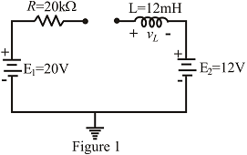
Fig. 11.80
Expert Solution & Answer

Trending nowThis is a popular solution!

Students have asked these similar questions
A relay has a 500-turn coil that draws 50 mA rms when a 60-Hz voltage of 24 V rms is applied. Assume that the resistance of the coil is negligible. Determine the peak flux linking the coil, the reluctance of the core, and the inductance of the coil.
Find value of voltage induced in a coil.
if a coil has 780 turns and a constant flux of 7mWb and a changing flux of 13mWb.
The self inductance of a coil of 500 turns is 0.25 H. If 60% of the flux is linked with second coil of 10,000 turns, then find the mutual inductance of the two coils.
Chapter 11 Solutions
Introductory Circuit Analysis
Ch. 11 - For the electromagnet in Fig. 11.75: a. Find the...Ch. 11 - For the inductor in Fig. 11.76, find the...Ch. 11 - a. Repeat Problem 2 with a ferromagnetic core with...Ch. 11 - For the inductor in Fig. 11.77, find the...Ch. 11 - An air-core inductor has a total inductance of 4.7...Ch. 11 - What are the inductance and the range of expected...Ch. 11 - If the flux linking a coil of 50 turns changes at...Ch. 11 - Determine the rate of change of flux linking a...Ch. 11 - How many turns does a coil have if 42 mV are...Ch. 11 - Find the voltage induced across a coil of 22 mH if...
Ch. 11 - For the circuit of Fig. 11.78 composed of standard...Ch. 11 - For the circuit in Fig. 11.79 composed of standard...Ch. 11 - For the network of Fig. 11.80. a. Write the...Ch. 11 - Give a supply of 18 V, use standard values to...Ch. 11 - For the circuit in Fig. 11.82: a. Write the...Ch. 11 - In this problem, the effect of reversing the...Ch. 11 - For the network of Fig. 11.84: a. Find the...Ch. 11 - Prob. 18PCh. 11 - Prob. 19PCh. 11 - Prob. 20PCh. 11 - For the network in Fig. 11.88: a. Determine the...Ch. 11 - For the network in Fig. 11.89: a. Write the...Ch. 11 - Prob. 23PCh. 11 - For Fig. 11.91: a. Determine the mathematical...Ch. 11 - For Fig. 11.92: a. Determine the mathematical...Ch. 11 - For the network in Fig. 11.93, the switch is...Ch. 11 - The switch in Fig. 11.94 has been open for a long...Ch. 11 - Prob. 28PCh. 11 - The switch for the network in Fig. 11.96 has been...Ch. 11 - The switch in Fig. 11.97 has been closed for a...Ch. 11 - Given iL=100mA(1e-t/20ms) a. Determine iLatt=1ms....Ch. 11 - a. If the measured current for an inductor during...Ch. 11 - The network in Fig. 11.98 employs a DMM with an...Ch. 11 - Find the waveform for the voltage induced across a...Ch. 11 - Find the waveform for the voltage induced across a...Ch. 11 - Prob. 36PCh. 11 - Find the total inductance of the circuit of Fig....Ch. 11 - Find the total inductance for the network of Fig....Ch. 11 - Reduce the network in Fig. 11.104 to the fewest...Ch. 11 - Reduce the network in Fig. 11.105 to the fewest...Ch. 11 - Reduce the network of Fig. 11.106 to the fewest...Ch. 11 - For the network in Fig. 11.107: a. Write the...Ch. 11 - For the network in Fig. 11.108: a. Write the...Ch. 11 - For the network in Fig. 11.109. a. Find the...Ch. 11 - Find the steady-state currents I1 and I2 for the...Ch. 11 - Find the steady-state currents and voltages for...Ch. 11 - Find the steady-state currents and voltages for...Ch. 11 - Find the indicated steady-state currents and...Ch. 11 - Prob. 49PCh. 11 - Using PSpice or Multisim, verify the results of...Ch. 11 - Using the PSpice or Multisim, find the solution to...Ch. 11 - Using PSpice or Multisim, find the solution to...Ch. 11 - Using PSpice or Multisim, verify the results of...
Knowledge Booster


Learn more about
Need a deep-dive on the concept behind this application? Look no further. Learn more about this topic, electrical-engineering and related others by exploring similar questions and additional content below.Similar questions
- A 70-Vac source has the following waveform. Determine:a. equation of the waveform (in time domain)b. the instantaneous voltage when t = 120 msc. the angle (1st occurrence) after t = 0 when the voltage is +80 Vd. the time (2nd occurrence) after t = 0 when the voltage is –10 Varrow_forwardWhen the waveform shown in fig. (1) is applied to true responding ac voltmeter, the output would be (5.314 V). If the same signal is applied to average responding ac voltmeter, what will be: 1. The indicate value. 2. The true value. 3. The true form factor. 4. The indicate crest factor.arrow_forwardA motor with 1mH of inductance and an unknown internal resistance is connected to a 100V RMS 10kHz source. The power factor has been corrected by adding a 247nF capacitor in parallel with the motor. Calculate the value of the internal resistance.arrow_forward
- A capacitance is rated 100 kVar, 380 volts, 50 hz. What will its rating be at 60 Hz 220 V?arrow_forwardSketch the waveform for i of the network of the figure if tt= 2ts and the total reverse recoverytime is 9 ns.arrow_forwardWhich of the following is not a green energy source? a. Tidal b. Nuclear c. Biomass d. wavearrow_forward
- An alternating voltage is represented by the expression v = 35 sin (314.2 t) volt. Determine, i) the maximum value, ii) the frequency, iii) the period of the waveform, and iv) the value 3.5 ms after it passes through zero, going positive. (b) i. Explain the types of semiconductors and the classifications of the semiconductor materials. ii. With the aid of a diagram, explain the formation of the P and N types of semiconductor.arrow_forwardCompute the instantaneous power absorbed by the inductance at t = 2 ms.arrow_forwardAn alternating current i is represented by i = 10 sin942t A. Determine (a) thefrequency, (b) the period, (c) the time taken from t = 0 for the current to reach a valueof 6A for a first and second time, (d) the energy dissipated when the current flowsthrough a 20 ohm resistor for 30 min.arrow_forward
- In the circuit below, if the inductance L is large enough to operate in continuous current mode. a) Draw the waveform of the output voltage and mains current for the 45 degree trigger angle when the switch S is in transmission. b) Average value of output DA voltage VDC1 when switch S is open, output DA when switch S is closed (in transmission) If the average value of the voltage is VDC2, calculate the value of VDC1 / VDC2. Lesson: power electronics please quickarrow_forwardA coil of inductance 2 Henrys and a resistance of 10 ohms is connected with an emf, E=200sin20t volts, where t is the time in seconds. I=0 when t=0. Find I when t=0.05 second.arrow_forwardA 50-cycle voltage with maximum value of 24 V. (a) What will be the value of the instantaneous voltage at 0.00175 sec after the wave passesthrough in positive direction? (b) what will be the equation of the instantaneous current, if a non-inductive resistor of 9 ohms is connectedto the voltage source?arrow_forward
arrow_back_ios
SEE MORE QUESTIONS
arrow_forward_ios
Recommended textbooks for you
 Introductory Circuit Analysis (13th Edition)Electrical EngineeringISBN:9780133923605Author:Robert L. BoylestadPublisher:PEARSON
 Delmar's Standard Textbook Of ElectricityElectrical EngineeringISBN:9781337900348Author:Stephen L. HermanPublisher:Cengage Learning
 Programmable Logic ControllersElectrical EngineeringISBN:9780073373843Author:Frank D. PetruzellaPublisher:McGraw-Hill Education
 Fundamentals of Electric CircuitsElectrical EngineeringISBN:9780078028229Author:Charles K Alexander, Matthew SadikuPublisher:McGraw-Hill Education
 Electric Circuits. (11th Edition)Electrical EngineeringISBN:9780134746968Author:James W. Nilsson, Susan RiedelPublisher:PEARSON
 Engineering ElectromagneticsElectrical EngineeringISBN:9780078028151Author:Hayt, William H. (william Hart), Jr, BUCK, John A.Publisher:Mcgraw-hill Education,
Introductory Circuit Analysis (13th Edition)
Electrical Engineering
ISBN:9780133923605
Author:Robert L. Boylestad
Publisher:PEARSON
Delmar's Standard Textbook Of Electricity
Electrical Engineering
ISBN:9781337900348
Author:Stephen L. Herman
Publisher:Cengage Learning
Programmable Logic Controllers
Electrical Engineering
ISBN:9780073373843
Author:Frank D. Petruzella
Publisher:McGraw-Hill Education
Fundamentals of Electric Circuits
Electrical Engineering
ISBN:9780078028229
Author:Charles K Alexander, Matthew Sadiku
Publisher:McGraw-Hill Education
Electric Circuits. (11th Edition)
Electrical Engineering
ISBN:9780134746968
Author:James W. Nilsson, Susan Riedel
Publisher:PEARSON
Engineering Electromagnetics
Electrical Engineering
ISBN:9780078028151
Author:Hayt, William H. (william Hart), Jr, BUCK, John A.
Publisher:Mcgraw-hill Education,
How do Universal Motors work ?; Author: Lesics;https://www.youtube.com/watch?v=0PDRJKz-mqE;License: Standard Youtube License