
Concept explainers
Videos
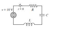
(a) Solve the equation for t in terms of L, R, C, and t, assuming that at t = 0, i = 0, and di/dt,= 8.
(b) Use the subs command to substitute L = 3 H. R = 10O, and C = 80 µF into the expression that was derived in part (a). Make a plot of i versus t for
(c) Use the subs command to substitute L = 3 H, R = 200 O, and C = l200µF into the expression that was derived in part (a). Make a plot of i versus t for
(d) Use the subs command to substitute L = 3 H, R = 201 O, and C = 300µF into the expression that was derived in pan (a). Make a plot of i versus t for
Want to see the full answer?
Check out a sample textbook solution
Chapter 11 Solutions
EBK MATLAB: AN INTRODUCTION WITH APPLIC


- For the circuit in Figure 3 the switch is in the left position for several minutes: (a) Find the Initlal voltage, V, on the capacitor just before the switch is flipped (b) Find an expression v(t) that describes the voltage across the 20 N resistor after the switch has been Figure 3 U 09 flipped to the right NOTE: Remember what we said in class: use a Circuit-Specific Equation to get a value you know. Then solve for whatever else the problem asks for +50 µF 380 0 20 2arrow_forwardAn LC circuit like the one in the Figure contains an 25.1-mH inductor and a 224-µF capacitor that initially carries a 212-μC charge. The switch is open for t < 0 and then thrown closed at t = 0. At t = 1.97-ms, find the current in the circuit (unit in mA). t C -ww- Larrow_forwardFor the circuit below with switch U1 closing at time t-0 and the initial current in L1 equal zero, find the transient response voltage across the inductor L1: R1 U1 100 V1 20Vde L1 2mHarrow_forward
- Assignment: RL & RC Circuits. R Figure 1: RL Circuit 1. In an RL series circuit containing only a resistor and inductor, Kirchhop's second law states that the sum of the voltage drop across the inductor(Ldi/dt) and the voltage drop across the resistor (iR) is the same as the impressed voltage (E(t)) on the circuit. The current i(t), called the response of the system, is governed by a differential equation di L + Ri = E(t) 'dt where L and R are constants known as inductance and the resistance respectively. Based on the above equation, solve the following: (a) A 12-volt battery is connected to a series in which the inductance is 0.5 henry and the resistance is 10 ohms. Determine the current i if the initial current is zero. Then determine the steady-state current for the system. Ans: i(t) = (1 –e-201) %3D (b) An electromotive force 0 20 120, E(t) = { 0, is applied to an LR series circuit in which the inductance is 20 henry and the resistance is 2 ohms. Find the current i(t) if i(0) = 0.…arrow_forwardThe switch S is closed at t = 0. Which statements about the following RL circuit are true? (Assume a DC source and that the inductors have no resistance.) Circle all answers that apply. L L R (A) Immediately after the switch is closed, the source sees an equivalent resistance of R/2. (B) Immediately after the switch is closed, the source sees an equivalent resistance of 2R. (C) Immediately after the switch is closed, the source sees an equivalent resistance of 3R/2. (D) At t = infinity after the switch is closed, the source sees an equivalent resistance of R. (E) At t = infinity after the switch is closed, the source sees an equivalent resistance of 2R. (F) At t = infinity after the switch is closed, the source sees an equivalent resistance of 3R/2.arrow_forwardThe capacitor in the circuit is initially uncharged and the switch S is suddenly closed at t=0. Find the current on resistor R: at to Take R₁-4R and R 3R. A) = B) 6 25 D) E) SIA R₂ FF R₁arrow_forward
- For the circuit shown in Figure Q2, determine the followi (a) The current in the inductors L1 and L2. (b) The voltage across the capacitors Cl and C2. (c) The total energy stored in the circuit. (d) The total power supplied by the source. 30V II RI -000-m 20mH 1052 50mH 2 R2 2002 300µF -000 30ml 91 300µF CI 600 μF R3 30Ω C3arrow_forwardIn the circuit shown in Figure, the switch S is closed at time t = 0. the voltage across the inductance at t = 0+ 352 10V A) 2V B) 4V C) -6V D 8V S m HIMM 112 4F ΔΩ 000arrow_forwardQuestion 14 A charged capacitor of C-67.0 µF is connected to a resistor of R=2.8 Mn as shown in the figure. The switch S is closed at time t-0. Find the time (in seconds) it takes the current to fall to 0.25 of its initial value. R wwwarrow_forward
- A charged capacitor of C-46.0 µF is connected to a resistor of R-2.8 M2 as shown in the figure. The switch S is closed at time 1-0. Find the time (in seconde) sakes the current to fall to 0.25 of its initial value. R wwwarrow_forwardGiven That: Is=0.0098, R1=60000, R2=6000 0, L=16 H, C=2 F, The circuit shown below under dc conditions find the following: L ell Is R1 R2 the current in L The voltage across capacitorarrow_forwardThe figure below shows a simple RC circuit with a 3.10-μF capacitor, a 3.60-MQ resistor, a 9.00-V emf, and a switch. What are the following exactly 8.50 s after the switch is closed? (a) the charge on the capacitor μC (b) the current in the resistor μA R (c) the rate at which the capacitor is storing energy μW (d) the rate at which the battery is delivering energy μWarrow_forward
 Introductory Circuit Analysis (13th Edition)Electrical EngineeringISBN:9780133923605Author:Robert L. BoylestadPublisher:PEARSON
 Delmar's Standard Textbook Of ElectricityElectrical EngineeringISBN:9781337900348Author:Stephen L. HermanPublisher:Cengage Learning
 Programmable Logic ControllersElectrical EngineeringISBN:9780073373843Author:Frank D. PetruzellaPublisher:McGraw-Hill Education
 Fundamentals of Electric CircuitsElectrical EngineeringISBN:9780078028229Author:Charles K Alexander, Matthew SadikuPublisher:McGraw-Hill Education
 Electric Circuits. (11th Edition)Electrical EngineeringISBN:9780134746968Author:James W. Nilsson, Susan RiedelPublisher:PEARSON
 Engineering ElectromagneticsElectrical EngineeringISBN:9780078028151Author:Hayt, William H. (william Hart), Jr, BUCK, John A.Publisher:Mcgraw-hill Education,