
Videos
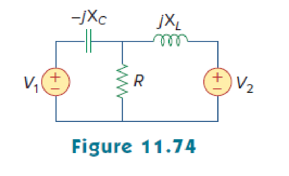
Using Fig. 11.74, design a problem to help other students better understand the conservation of AC power.
Design a problem to make the better understand of conservation of AC power.
Explanation of Solution
Problem design:
In Figure 11.74, consider the value of capacitive reactance
Formula used:
Write the expression to find the complex power.
Here,
Write the expression for the impedance
Here,
R is the value of resistance, and
X is the value of reactance.
Calculation:
Refer to Figure 11.74 in the textbook.
The given circuit is modified as shown in Figure 1.
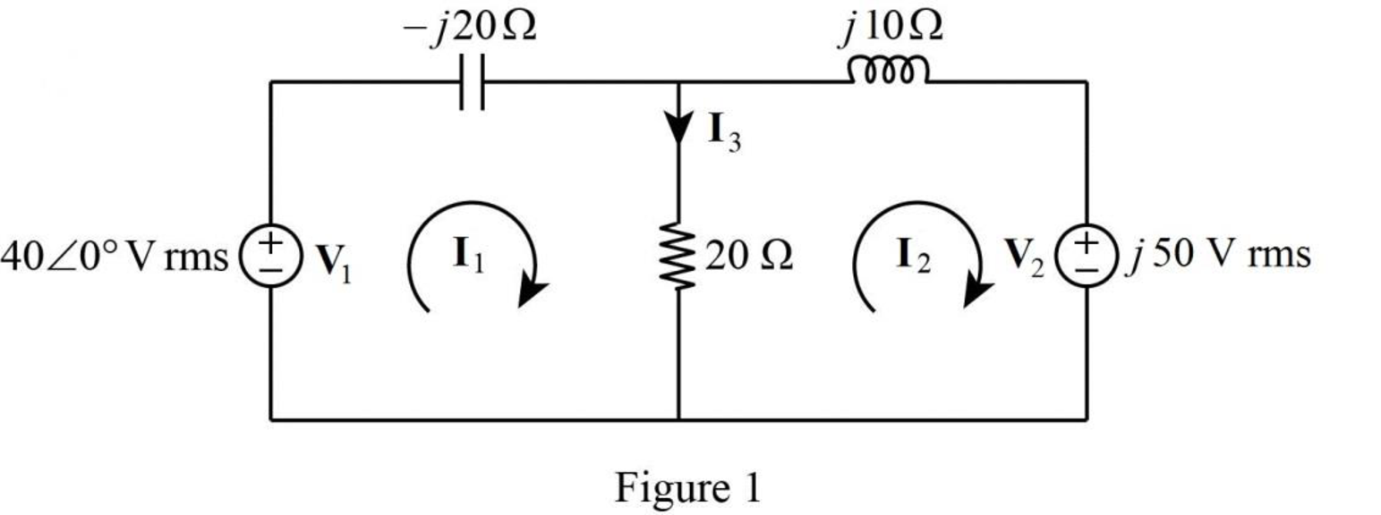
In Figure 1, apply Kirchhoff’s voltage law for loop 1 as follows.
In Figure 1, apply Kirchhoff’s voltage law for loop 2 as follows.
Put equation (3) and (4) in matrix form as follows,
Evaluate the determinant
Evaluate the determinant
Evaluate the determinant
In Figure 1, the current
Substitute
The magnitude of current
In Figure 2, the current
Substitute
The magnitude of current
The current
Substitute
The magnitude of current
The complex power absorbed by the
Substitute
From Figure (1), the impedance of capacitance is,
The complex power absorbed by the capacitor is,
Substitute
The complex power absorbed by the resistor is,
Substitute
From Figure (1), the impedance of inductance is,
The complex power absorbed by the inductor is,
Substitute
The complex power absorbed by the
Substitute
Therefore, the complex power absorbed by the
Conclusion:
Thus, a problem is designed and solved for the better understand of conservation of AC power.
Want to see more full solutions like this?
Chapter 11 Solutions
FUNDAMENTALS OF ELEC.CIRC.(LL) >CUSTOM<


- A DC generator supplies current to 40 lamps with a power of each60 Watts each. Calculate the current IL. Calculate the magnitude of the voltage generated by the generator in problem 1, if Ra = 0.1 Ohm and Rsh = 50 Ohmarrow_forwardA two-pole three-phase 50 Hz Y-connected AC generator has 9 slots per pole and 6 conductors per slot. What is the flux per pole if the voltage on open circuit is 1.1 kV. Assume a coil span of unity.arrow_forwardThe maximum values of voltage and current outputs of an alternator are 300V and 20A, respectively. What is the power output in watts if the voltage leads the current by 30 degrees? THE ANSWER SHOULD BE 2598 W.arrow_forward
- The power factor of a certain load is improved to 0.92 lagging with the addition of a 30 kVAR bank of capacitors. If the resulting supply apparent power is 200 kVA, determine the power factor before correction.arrow_forwardpower factor on 1100 V, 50 Hz mains. The power factor of the system is improved from 0.6 lagging to 0.95 lagging by using a capacitor bank embedded in delta. Assuming the KVA of the load remains constant, indicate the rating of the capacitor and find how much additional kW can be obtained. And If the capacitor bank is connected in star, indicate the rating of the capacitorarrow_forwardCompare and contrast diesel power plant with one of the existing power plant in the country in terms of: a. Efficiencyarrow_forward
- A series generator delivers a power of 6.25kW and a load resistance of 250. If R_{A} = 0.05ohms and R_{s} = 0.025ohms , calculate the generated emf.arrow_forwardA load of 500 kVA operates on 1100 V, 50 Hz mains with power factor of 0.6 lagging. It is required to improve the power factor to 0.95 lagging by using the star connected capacitor bank. Assuming that the load KVA remains constant, suggest the rating of the capacitors.arrow_forwardA wind turbine system has an average overall efficiency of 25%, what is the size of wind rotor is required if 100 watt DC generator will be driven? The average expected wind velocity at the rotor is 8 m/s.arrow_forward
- 2. The series is shown in the picture below, i(t) = 2 + 10 Cos(t+10° ) + 6 Cos(3t + 35°) Amperre., Calculate the average power it is transmitted from the current source i(t).arrow_forwardA 400V, 3-phase Induction motor has input power of 18 KW and operates at power factor of 0.87 lagging with an efficiency of 89 % Calculate the reading on each of the two wattmeter connected to measure the input. W1 W2arrow_forwardThe voltage v = 207 sin(100t+50°) V is connected acroos a 5-H inductor. Determine the inductive reactance. Write the magnitude only in four decimal places.arrow_forward
 Introductory Circuit Analysis (13th Edition)Electrical EngineeringISBN:9780133923605Author:Robert L. BoylestadPublisher:PEARSON
 Delmar's Standard Textbook Of ElectricityElectrical EngineeringISBN:9781337900348Author:Stephen L. HermanPublisher:Cengage Learning
 Programmable Logic ControllersElectrical EngineeringISBN:9780073373843Author:Frank D. PetruzellaPublisher:McGraw-Hill Education
 Fundamentals of Electric CircuitsElectrical EngineeringISBN:9780078028229Author:Charles K Alexander, Matthew SadikuPublisher:McGraw-Hill Education
 Electric Circuits. (11th Edition)Electrical EngineeringISBN:9780134746968Author:James W. Nilsson, Susan RiedelPublisher:PEARSON
 Engineering ElectromagneticsElectrical EngineeringISBN:9780078028151Author:Hayt, William H. (william Hart), Jr, BUCK, John A.Publisher:Mcgraw-hill Education,