
Concept explainers
Videos
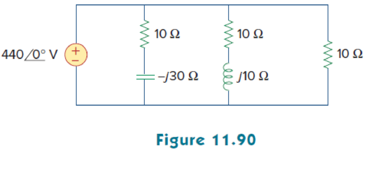
Consider the power system shown in Fig. 11.90. Calculate:
- (a) the total complex power
- (b) the power factor
- (c) the parallel capacitance necessary to establish a unity power factor
(a)
Calculate the complex power of the circuit shown in Figure 11.90.
Answer to Problem 75P
The total complex power for the given circuit is
Explanation of Solution
Given data:
Refer to Figure 11.90 in the textbook.
The voltage
The capacitance C is
The inductance L is
Formula used:
Write the expression to find the complex power.
Here,
Write the expression to find the complex power.
Here,
Calculation:
Refer to figure 11.90 in the textbook.
Consider the impedance
Consider the impedance
Consider the impedance
Substitute
Substitute
Substitute
The total complex power is,
Substitute
Comparing the above equation with equation (1).
Hence, the total complex power is,
Conclusion:
Thus, the total complex power for the given circuit is
(b)
Find the power factor for the given circuit.
Answer to Problem 75P
The power factor for the given circuit is
Explanation of Solution
Given data:
The voltage
From Part (a),
The real power and the reactive power is,
Formula used:
Write the expression to find the power factor
Here,
Write the expression for phase angle
Calculation:
Substitute
Substitute
Conclusion:
Thus, the power factor for the given circuit is
(c)
Find the parallel capacitance value required to establish a unity power factor.
Answer to Problem 75P
The value of capacitance is
Explanation of Solution
Given data:
The voltage
Formula used:
Write the expression to find the value of the capacitance.
Here,
Calculation:
Consider the frequency is
From equation (3), the reactive power is,
Substitute
Simplify the equation as follows,
Conclusion:
Thus, the value of capacitance is
Want to see more full solutions like this?
Chapter 11 Solutions
FUNDAMENTALS OF ELECTRIC...(LL)>CUSTOM<


- The impedance of an electrical circuit is (30 − j50) ohms. Determine (a) the resistance, (b) the capacitance, (c) the modulus of the impedance, and (d) the current flowing and its phase angle, when the circuit is connected to a 240V, 50 Hz supply.arrow_forwardA series generator delivers a power of 6.25kW and a load resistance of25Ω. If RA=0.05Ω and RS=0.025Ω, calculate the generated emf.arrow_forwardThe power of a certain CD player operating at 120 V rms is20.0 W. Assuming that the CD player behaves like a pure resistor, find the maximum instantaneous powerarrow_forward
- Determine the total complex, apparent, average, and reactive power. Sketch the power trianglearrow_forwardThe voltage v = 207 sin(100t+50°) V is connected acroos a 5-H inductor. Determine the inductive reactance. Write the magnitude only in four decimal places.arrow_forwardAn industrial plant consists of several induction motors. The plant absorbs 300 kW at 0.6 PF lagging from the substation bus. Compute the required kVAR rating of the capacitor connected across the load toraise the power factor to 0.9 lagging. A 200-hp, 90% efficiency, synchronous motor is operated from the same busat rated conditions and 0.8 power factor leading. Calculate the resulting powerfactor.arrow_forward
- If the apparent power of a source is known, then the power factor, active and reactive powers can be calculated from it. Select one: True Falsearrow_forwardWhen connected to a 120 V (rms), 60-Hz power line, a load absorbs 4kW at a lagging power factor of 0.8. Find the value of Capacitance, C, necessary to raise the power factor to 0.95 lagging.arrow_forwardA 3- phase , 50 Hz, 400 motor develops 100 H.P. ( 74.6 kW ), the power factor being 0.75 lagging and efficiency 93%. A bank of capacitors is connected in delta across the supply terminals and power factor raised to 0.95 lagging . Each of the capacitance units is built of 4 similar 100 V capacitors . Determine the capacitance of each capacitor .arrow_forward
- : A single phase motor operating off a 400V, 50Hz supply is developing 10KW with an efficiency of 84% and a power factor (p.f) of 0.7 lagging. Calculate; The input apparent power; The active and reactive components of the current; The reactive power (in kilovars).arrow_forwardProblem 11.34. At full load, a commercially available 106 hp, three-phase induction motor operates at an efficiency of 96% and a power factor of 0.87 lag. The motor is supplied from a three-phase outlet with a line-voltage rating of 208 V. 1. What is the magnitude of the line current in Ampere drawn from the 208 V outlet? (1 hp = 746 W). 2. Calculate the reactive power in kVAR supplied to the motor.arrow_forward2) The net inlet to a factory powered by a 2300 volt infinite busis measured as 765 A, for a lag 0.92 power factor. although mostloads is inductive, the input power factor has been improved by installing asynchronous capacitor operating at its nominal value of 1000 KVA. Determine the factor oforiginal factory power.arrow_forward
 Introductory Circuit Analysis (13th Edition)Electrical EngineeringISBN:9780133923605Author:Robert L. BoylestadPublisher:PEARSON
 Delmar's Standard Textbook Of ElectricityElectrical EngineeringISBN:9781337900348Author:Stephen L. HermanPublisher:Cengage Learning
 Programmable Logic ControllersElectrical EngineeringISBN:9780073373843Author:Frank D. PetruzellaPublisher:McGraw-Hill Education
 Fundamentals of Electric CircuitsElectrical EngineeringISBN:9780078028229Author:Charles K Alexander, Matthew SadikuPublisher:McGraw-Hill Education
 Electric Circuits. (11th Edition)Electrical EngineeringISBN:9780134746968Author:James W. Nilsson, Susan RiedelPublisher:PEARSON
 Engineering ElectromagneticsElectrical EngineeringISBN:9780078028151Author:Hayt, William H. (william Hart), Jr, BUCK, John A.Publisher:Mcgraw-hill Education,