
Concept explainers
Videos
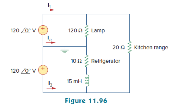
A regular household system of a single-phase three-wire circuit allows the operation of both 120-V and 240-V, 60-Hz appliances. The household circuit is modeled as shown in Fig. 11.96. Calculate:
- (a) the currents I1, I2, and In
- (b) the total complex power supplied
- (c) the overall power factor of the circuit
(a)
Find the currents
Explanation of Solution
Given data:
Refer to Figure 11.96 in the textbook.
The frequency
The circuits performs at both the voltages
The inductance L is
Formula used:
Write the expression for reactance of an inductor
Here,
L is the inductance.
Calculation:
Refer to Figure 11.96 in the textbook.
Substitute
The modified Figure is shown in Figure 1.
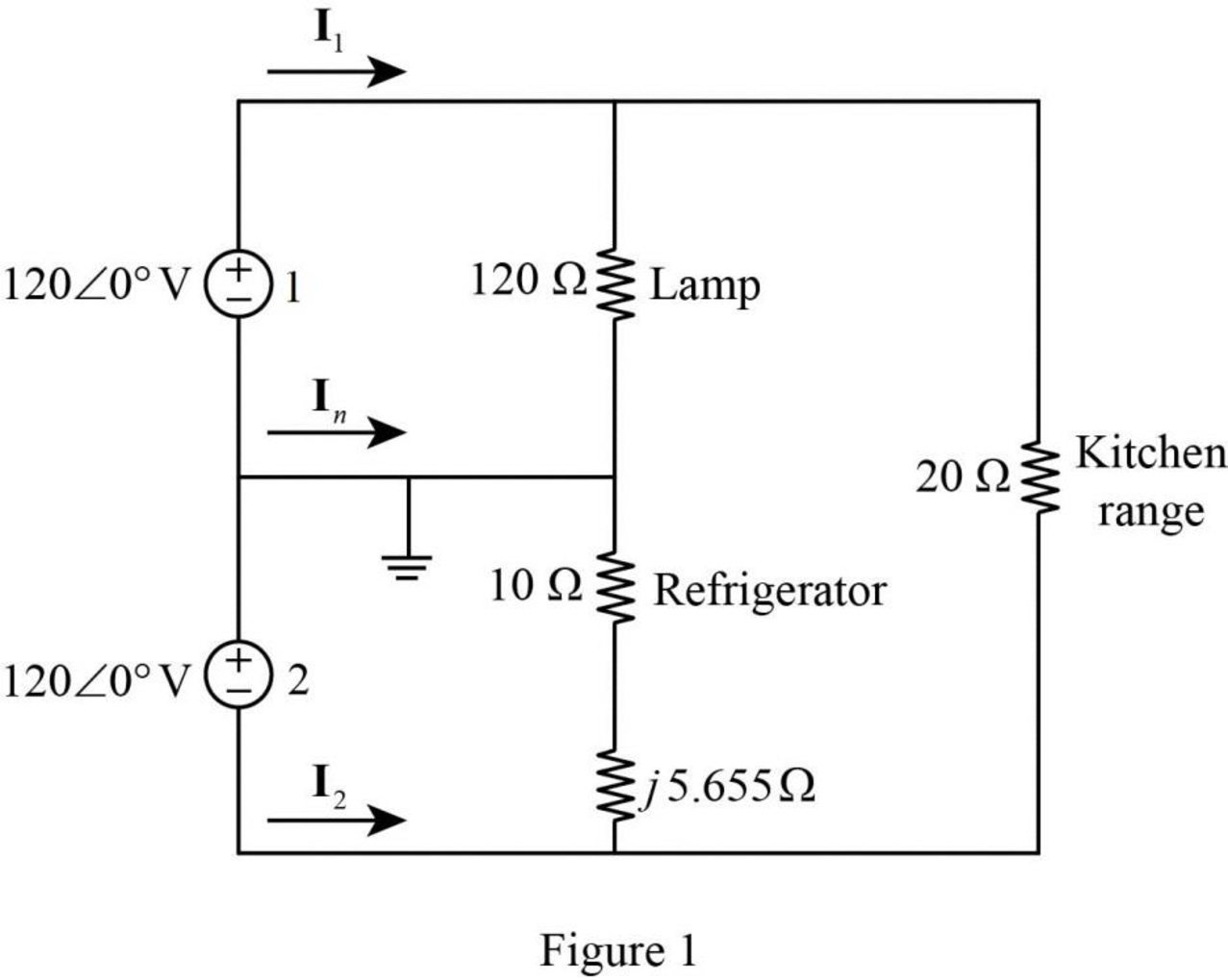
In Figure 1, the current flowing through the lamp
The current flowing through the refrigerator is calculated by using Ohm’s law as follows.
Convert the equation from polar to rectangular form.
The current flowing through the kitchen range
In Figure, apply Kirchhoff’s current law in the circuit. Therefore, the current
Similarly, the current
Convert the equation from rectangular to polar form.
Similarly, the current
Convert the equation from rectangular to polar form.
Conclusion:
Thus, the currents
(b)
Find the total complex power in the circuit of Figure 11.96.
Answer to Problem 85P
The total complex power is
Explanation of Solution
Given data:
Refer to Figure 11.96 in the textbook.
From part (a),
Calculation:
Refer to Figure 1 shown in Part (a).
The complex power delivered by the voltage source 1 is,
Substitute
The complex power delivered by voltage source 2 is,
Substitute
Simply the equation as follows,
Convert the equation from polar to rectangular form.
The total complex power is,
Substitute
Conclusion:
Thus, the total complex power is
(c)
Find the total power factor of the circuit shown in Figure 11.96.
Answer to Problem 85P
The total power factor of the circuit is 0.9888 (lagging).
Explanation of Solution
Given data:
Refer to Figure 11.96 in the textbook.
Formula used:
Write the expression for complex power.
Here,
P is the real power, and
Q is the reactive power.
Write the expression for power factor.
Calculation:
On comparing equation (2) and (3), the real power is,
From equation (2), the apparent power S is,
Substitute
Since,
Conclusion:
Thus, the total power factor of the circuit is 0.9888 (lagging).
Want to see more full solutions like this?
Chapter 11 Solutions
FUNDAMENTALS OF ELECTRIC...(LL)>CUSTOM<


- 2) The net inlet to a factory powered by a 2300 volt infinite busis measured as 765 A, for a lag 0.92 power factor. although mostloads is inductive, the input power factor has been improved by installing asynchronous capacitor operating at its nominal value of 1000 KVA. Determine the factor oforiginal factory power.arrow_forwardA 3-phase, 50 Hz, 3000 V motor develops 600 H.P. (447·6 kW), the power factor being 0·75 lagging and the efficiency 0·93. A bank of capacitors is connected in delta across the supply terminals and power factor raised to 0·9 lagging. Each of the capacitance units is built of five similar 600-V capacitors. Determine the leading Kvar taken by each three sets.arrow_forwardA 100KVA, 220V, a star-connected alternator is loaded at full load and at 60% pf lagging.The effective AC resistance per phase is 0.01411Ω. If the synchronous reactance is 4.5times the effect of the armature leakage reactance wherein the later is 0.046 Ω perphase, find(a) the phase voltage that would be generated at the load if the circuit were operating normally(b) What no-load open-circuit phase voltage must be present in order to circulate full-load current in short-circuit state while maintaining the same speed and field current?(c) What is the terminal phase voltage of the alternator when it is under a shorted load condition? Give an explanation in support of your response using just one sentence. The IA phasor should be used as the reference one.arrow_forward
- At full load, a commercially available 100 hp, three-phase induction motor operates at an efficiency of 97% and a power factor of 0.88 lag. The motor is supplied from a three-phase outlet with a linevoltage rating of 208 V. 1. a) What is the magnitude of the line current drawn from the 208 V outlet? (1 hp=746 W.) 2. b) Calculate the reactive power supplied to the motor.arrow_forwardDesign a power factor correction circuit with the value of parallel capacitance needed tocorrect a load of 179 kVAR at 0.85 lagging pf to unity pf. Assume that the load issupplied by a 110-V (rms), 60-Hz line.arrow_forwarda power station has a connected load of 48MW. the energy generated for the year is 61500MWh. if the station has a load factor of 35%. solve the demand factor of the station. Subject: Distribution System and Substation Designarrow_forward
- A three-phase system includes a 346.4 V line-to-line supplying a three-phase motor rated 15KVA 0.8pf lag plus additional balanced constant impedance loads. The single-phase representation of the system is shown below. Assume that sources and loads are Y-connected. 1. What is the RMS value of the line current, I in A? 2. If this set of loads will be supplied through a service transformer. What should the minimum size of the transformer in kVA? 3. What should be the size of three-phase capacitor(that will be added to the load mix) to improve power factor to almost 0.95 lag?arrow_forwardA load of 500 kVA operates at 0.6 lagging power factor on 1100V, 50 Hz mains. The power factor of the system is improved from 0.6 lagging to 0.95 lagging by using a delta connected capacitor bank. Assuming VA of the load remains constant, indicate the rating of the capacitor and find the additional kW that can be obtained.arrow_forwardA load of 500 kVA operates at 0.6 lagging power factor on 1100 V, 50 Hz mains. The power factor of the system is improved from 0.6 lagging to 0.95 lagging by using a capacitor bank connected in delta. Assuming the KVA of the load remains constant, indicate the rating of the capacitor and find how much additional kW can be obtained.arrow_forward
- If a 3- Ø, Y-connected system has a line-to-line voltage of 1103Sin(377t) V, then the line-to-neutral (RMS) voltage would be:arrow_forwardFor the circuit in Fig. 11.47, find the value of ZL that will receive the maximum power from the circuit. Then calculate the power delivered to the load ZL.arrow_forwardpower factor on 1100 V, 50 Hz mains. The power factor of the system is improved from 0.6 lagging to 0.95 lagging by using a capacitor bank embedded in delta. Assuming the KVA of the load remains constant, indicate the rating of the capacitor and find how much additional kW can be obtained. And If the capacitor bank is connected in star, indicate the rating of the capacitorarrow_forward
 Introductory Circuit Analysis (13th Edition)Electrical EngineeringISBN:9780133923605Author:Robert L. BoylestadPublisher:PEARSON
 Delmar's Standard Textbook Of ElectricityElectrical EngineeringISBN:9781337900348Author:Stephen L. HermanPublisher:Cengage Learning
 Programmable Logic ControllersElectrical EngineeringISBN:9780073373843Author:Frank D. PetruzellaPublisher:McGraw-Hill Education
 Fundamentals of Electric CircuitsElectrical EngineeringISBN:9780078028229Author:Charles K Alexander, Matthew SadikuPublisher:McGraw-Hill Education
 Electric Circuits. (11th Edition)Electrical EngineeringISBN:9780134746968Author:James W. Nilsson, Susan RiedelPublisher:PEARSON
 Engineering ElectromagneticsElectrical EngineeringISBN:9780078028151Author:Hayt, William H. (william Hart), Jr, BUCK, John A.Publisher:Mcgraw-hill Education,