Videos
A gas refrigeration system using air as the working fluid has a pressure ratio of 5. Air enters the compressor at 0°C. The high-pressure air is cooled to 35°C by rejecting heat to the surroundings. The refrigerant leaves the turbine at −80°C and then it absorbs heat from the refrigerated space before entering the regenerator. The mass flow rate of air is 0.4 kg/s. Assuming isentropic efficiencies of 80 percent for the compressor and 85 percent for the turbine and using constant specific heats at room temperature, determine (a) the effectiveness of the regenerator, (b) the rate of heat removal from the refrigerated space, and (c) the COP of the cycle. Also, determine (d) the refrigeration load and the COP if this system operated on the simple gas refrigeration cycle. Use the same compressor inlet temperature as given, the same turbine inlet temperature as calculated, and the same compressor and turbine efficiencies.
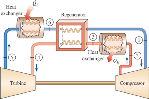
FIGURE P11–79
(a)
The effectiveness of the regenerator.
Answer to Problem 79P
The effectiveness of the regenerator is
Explanation of Solution
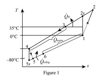
Show the T-s diagram as in Figure (1).
Express the temperature at state 2s.
Here, temperature at state 1 is
Express the temperature at state 2 from the isentropic relations.
Here, isentropic efficiency is
Express temperature at state 5s.
Here, temperature at state 4 is
Express temperature at state 4.
Here, thermal efficiency is
Express the temperature at state 6 using an energy balance.
Here, mass flow rate is
Express the effectiveness of the regenerator.
Here, enthalpy at state 3, 4 and 6 is
Conclusion:
Perform unit conversion of temperature at state 1, 3, and 5 from
Refer Table A-2, “ideal gas specific heats of various common gas”, and write the properties of air.
Substitute
Substitute
Substitute
Substitute
Solve Equations (VII) and (VIII) simultaneously by online calculator to get,
Substitute
Substitute
Hence, the effectiveness of the regenerator is
(b)
The rate of heat removal from the refrigerated space.
Answer to Problem 79P
The rate of heat removal from the refrigerated space is
Explanation of Solution
Express the rate of heat removal from the refrigerated space.
Conclusion:
Substitute
Hence, the rate of heat removal from the refrigerated space is
(c)
The COP of the gas refrigeration cycle.
Answer to Problem 79P
The COP of the gas refrigeration cycle is
Explanation of Solution
Express the net work input of the compressor.
Express the net work output of the turbine.
Express the coefficient of performance of the gas refrigeration cycle.
Conclusion:
Substitute
Substitute
Substitute
Hence, the COP of the gas refrigeration cycle is
(d)
The refrigeration load and the COP of the system.
Answer to Problem 79P
The refrigeration load is
Explanation of Solution
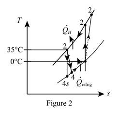
Show the T-s diagram as in Figure (2).
Express temperature at state 4s.
Here, temperature at state 3 is
Express temperature at state 4.
Express the refrigeration load.
Express the net work input.
Express the coefficient of performance of the system.
Conclusion:
Substitute
Substitute
Substitute
Hence, the refrigeration load is
Substitute
Substitute
Hence, the coefficient of performance of the system is
Want to see more full solutions like this?
Chapter 11 Solutions
Thermodynamics: An Engineering Approach


- Consider a refrigeration system using refrigerant-134a as the working fluid. If this refrigerator is to operate in an environment at 20°C, what is the minimum pressure to which the refrigerant should be compressed? Why?arrow_forwardAn air conditioner using refrigerant-134a as the working fluid is used to keep the temperature of a room at 23°C by giving heat to the external environment at 37°C. The heat gain of the house from the walls and windows is 250 kJ/min; 900 W heat is emitted into the room from the computer, TV and lamps. The refrigerant enters the compressor with a flow rate of 100 L/min in the form of saturated vapor at 400 kPa pressure and leaves the compressor at 70°C at 1200 kPa pressure.a) Draw the cycle by showing the elements of the cycle.b) the actual COP value,c) The highest COP value,d) The smallest refrigerant can have for the same compressor inlet and outlet conditions.Calculate the volumetric flow.arrow_forwardA commercial refrigerator with refrigerant-134a as the working fluid is used to keep the refrigerated space at 10°C by rejecting waste heat to cooling water that enters the condenser at 18°C at a rate of 0.25 kg/s and leaves at 26°C. The refrigerant enters the condenser at 1.2 MPa and 50°C and leaves at the same pressure subcooled by 5°C. If the compressor consumes 2.3 kW of power, determine the COP?arrow_forward
- A refrigerated room is kept at −18◦C by a vapor-compression cycle with R-134a as the refrigerant. Heat is rejected to cooling water that enters the condenser at 14◦C at a rate of 0.35 kg/s and leaves at 22◦C. The refrigerant enters the condenser at 1.2MPa and 50◦C and leaves at the same pressure subcooled by 5◦C. If the compressor consumes 5.5 kW of power, determine (a) the mass flow rate of the refrigerant, (b) the refrigeration load and the COP, (c) the second-law efficiency of the refrigerator and the total exergy destruction in the cycle, and (d) the exergy destruction in the condenser. Take specific heat of water to be 4.18 kJ/kg·◦C.arrow_forwardA commercial refrigerator with refrigerant-134a as the working fluid is used to keep the refrigerated space at –30°C by rejecting its waste heat to cooling water that enters the condenser at 18°C at a rate of 0.25 kg/s and leaves at 26°C. The refrigerant enters the condenser at 1.2 MPa and 65°C and leaves at 42°C. The inlet state of the compressor is 60 kPa and –34°C and the compressor is estimated to gain a net heat of 450 W from the surroundings. Determine the theoretical maximum refrigeration load for the same power input to the compressor. Water 26°C ↑ 18°C 1.2 MPа 42°C 65°C Condenser Expansion Win valve Evaporator Compressor 60 kPa -34°Carrow_forwardRefrigerant-134a enters the compressor of a refrigerator at 0.14MPa and -10°C at a rate of 0.05 kg/s and leaves at 0.8 MPa and 50°C. The refrigerant is cooled in the condenser to 26°C and 0.72 MPa and is throttled to 0.15 MPa. Determine (a) the rate of heat removal from the refrigerated space and the power input to the compressor, (b) the isentropic efficiency of the compressor, and (c) the coefficient of performance of the refrigerator. Answers: (a) 7.93 kW, 2.02 kW, (b) 0.939, (c) 3.93arrow_forward
- Consider a 300 kJ/min refrigeration system that operates on an ideal vapor-compression refrigeration cycle with refrigerant-134a as the working fluid. The refrigerant enters the compressor as saturated vapor at 140 kPa and is compressed to 800 kPa. Show the cycle on a T-s diagram with respect to saturation lines, and determine (a) the quality of the refrigerant at the end of the throttling process, (b) the coefficient of performance, and (c) the power input to the compressor.arrow_forwardA commercial refrigerator with refrigerant-134a as the working fluid is used to keep the refrigerated space at –35°C by rejecting waste heat to cooling water that enters the condenser at 18°C at a rate of 0.25 kg/s and leaves at 26°C. The refrigerant enters the condenser at 1.2 MPa and 50°C and leaves at the same pressure subcooled by 5°C. If the compressor consumes 3.3 kW of power, determine the mass flow rate of the refrigerant,arrow_forwardA commercial refrigerator with refrigerant-134a as the working fluid is used to keep the refrigerated space at –35°C by rejecting waste heat to cooling water that enters the condenser at 18°C at a rate of 0.25 kg/s and leaves at 26°C. The refrigerant enters the condenser at 1.2 MPa and 50°C and leaves at the same pressure subcooled by 5°C. If the compressor consumes 3.3 kW of power, determine the refrigeration load.arrow_forward
- A commercial refrigerator with refrigerant-134a as the working fluid is used to keep the refrigerated space at –35°C by rejecting waste heat to cooling water that enters the condenser at 18°C at a rate of 0.25 kg/s and leaves at 26°C. The refrigerant enters the condenser at 1.2 MPa and 50°C and leaves at the same pressure subcooled by 5°C. If the compressor consumes 3.3 kW of power, determine the minimum power input to the compressor for the same refrigeration load.arrow_forwardA refrigerator uses R-134a as the working fluid and operates on an ideal vapor compression cycle between 0.14 MPa and 0.8 MPa. If the mass flow rate of the refrigerant is 0.06 kg/s, determine (a) the rate of heat removal from the refrigerated space, (b) the power input to the compressor, (c) the heat rejection rate in the condenser, and (d) the COP.arrow_forward2. A steam power plant operates on the Rankine cycle in which the steam enters the turbine at 16 MPa and 600°C and the condensate leaves the condenser at 10 kPa. If the isentropic efficiency of the turbine is 87 percent and the isentropic efficiency of the pump is 85 percent, determine (a) the thermal efficiency of the cycle and (b) the net power output of the plant for a mass flow rate of 15 kg/s.arrow_forward
 Refrigeration and Air Conditioning Technology (Mi...Mechanical EngineeringISBN:9781305578296Author:John Tomczyk, Eugene Silberstein, Bill Whitman, Bill JohnsonPublisher:Cengage Learning