Package: Loose Leaf For Mechanics Of Materials With 1 Semester Connect Access Card
7th Edition
ISBN: 9781259290527
Author: BEER
Publisher: MCG
expand_more
expand_more
format_list_bulleted
Videos
Textbook Question
Chapter 11.5, Problem 47P
The 48-kg collar G is released from rest in the position shown and is stopped by plate BDF that is attached to the 20-mm-diameter steel rod CD and to the 15-mm-diameter steel rods AB and EF. Knowing that for the grade of steel used σall = 180 MPa and E = 200 GPa, determine the largest allowable distance h.
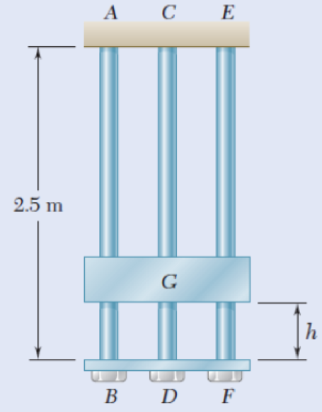
Fig.p11.47
Expert Solution & Answer

Trending nowThis is a popular solution!

Students have asked these similar questions
13.61
A bumper composed of three springs is to stop a 40Mg boxcar which is traveling at 1.2m/s as shown. One of the springs is 88mm shorter than the other two. The modulus of the shorter spring is 1.5MN/m while the modulus of the longer two springs is 1MN/m. Determine the maximum deflection of the bumper.
From mechanics of materials it is known that for a cantilever beam of constant cross section a static load P applied at end B will cause a deflection δB = PL3/3EI, where L is the length of the beam, E is the modulus of elasticity, and I is the moment of inertia of the cross-sectional area of the beam. Knowing that L = 10 ft, E = 29 x 106 lb/in2, and I = 12.4 in4, determine (a) the equivalent spring constant of the beam, (b) the frequency of vibration of a 520-lb block attached to end B of the same beam.
7
The coefficient of restitution (e) describes the extent to which the deformation during impact is elastic (e = 1) vs. plastic (e = 0).
True
False
Chapter 11 Solutions
Package: Loose Leaf For Mechanics Of Materials With 1 Semester Connect Access Card
Ch. 11.3 - Determine the modulus of resilience for each of...Ch. 11.3 - Determine the modulus of resilience for each of...Ch. 11.3 - Determine the modulus of resilience for each of...Ch. 11.3 - Determine the modulus of resilience for each of...Ch. 11.3 - The stress-strain diagram shown has been drawn...Ch. 11.3 - The stress-strain diagram shown has been drawn...Ch. 11.3 - Prob. 7PCh. 11.3 - Prob. 8PCh. 11.3 - Using E = 29 106 psi, determine (a) the strain...Ch. 11.3 - Using E = 200 GPa, determine (a) the strain energy...
Ch. 11.3 - A 30-in. length of aluminum pipe of...Ch. 11.3 - A single 6-mm-diameter steel pin B is used to...Ch. 11.3 - Prob. 13PCh. 11.3 - Prob. 14PCh. 11.3 - The assembly ABC is made of a steel for which E =...Ch. 11.3 - Show by integration that the strain energy of the...Ch. 11.3 - Prob. 17PCh. 11.3 - Prob. 18PCh. 11.3 - Prob. 19PCh. 11.3 - 11.18 through 11.21 In the truss shown, all...Ch. 11.3 - Prob. 21PCh. 11.3 - Each member of the truss shown is made of aluminum...Ch. 11.3 - Each member of the truss shown is made of aluminum...Ch. 11.3 - 11.24 through 11.27 Taking into account only the...Ch. 11.3 - Prob. 25PCh. 11.3 - 11.24 through 11.27 Taking into account only the...Ch. 11.3 - 11.24 through 11.27 Taking into account only the...Ch. 11.3 - Prob. 28PCh. 11.3 - Prob. 29PCh. 11.3 - Prob. 30PCh. 11.3 - 11.30 and 11.31 Using E = 200 GPa, determine the...Ch. 11.3 - Assuming that the prismatic beam AB has a...Ch. 11.3 - Prob. 33PCh. 11.3 - The design specifications for the steel shaft AB...Ch. 11.3 - Show by integration that the strain energy in the...Ch. 11.3 - The state of stress shown occurs in a machine...Ch. 11.3 - Prob. 37PCh. 11.3 - The state of stress shown occurs in a machine...Ch. 11.3 - Prob. 39PCh. 11.3 - Prob. 40PCh. 11.3 - Prob. 41PCh. 11.5 - A 5-kg collar D moves along the uniform rod AB and...Ch. 11.5 - The 18-lb cylindrical block E has a horizontal...Ch. 11.5 - The cylindrical block E has a speed v0 =16 ft/s...Ch. 11.5 - Prob. 45PCh. 11.5 - Prob. 46PCh. 11.5 - The 48-kg collar G is released from rest in the...Ch. 11.5 - Prob. 48PCh. 11.5 - Prob. 49PCh. 11.5 - Prob. 50PCh. 11.5 - Prob. 51PCh. 11.5 - The 2-kg block D is dropped from the position...Ch. 11.5 - The 10-kg block D is dropped from a height h = 450...Ch. 11.5 - Prob. 54PCh. 11.5 - A 160-lb diver jumps from a height of 20 in. onto...Ch. 11.5 - Prob. 56PCh. 11.5 - A block of weight W is dropped from a height h...Ch. 11.5 - 11.58 and 11.59 Using the method of work and...Ch. 11.5 - 11.58 and 11.59 Using the method of work and...Ch. 11.5 - 11.60 and 11.61 Using the method of work and...Ch. 11.5 - 11.60 and 11.61 Using the method of work and...Ch. 11.5 - 11.62 and 11.63 Using the method of work and...Ch. 11.5 - 11.62 and 11.63 Using the method of work and...Ch. 11.5 - Using the method of work and energy, determine the...Ch. 11.5 - Using the method of work and energy, determine the...Ch. 11.5 - The 20-mm diameter steel rod BC is attached to the...Ch. 11.5 - Torques of the same magnitude T are applied to the...Ch. 11.5 - Prob. 68PCh. 11.5 - The 20-mm-diameter steel rod CD is welded to the...Ch. 11.5 - The thin-walled hollow cylindrical member AB has a...Ch. 11.5 - 11.71 and 11.72 Each member of the truss shown has...Ch. 11.5 - 11.71 and 11.72 Each member of the truss shown has...Ch. 11.5 - Each member of the truss shown is made of steel...Ch. 11.5 - Each member of the truss shown is made of steel....Ch. 11.5 - Each member of the truss shown is made of steel...Ch. 11.5 - The steel rod BC has a 24-mm diameter and the...Ch. 11.9 - 11.77 and 11.78 Using the information in Appendix...Ch. 11.9 - 11.77 and 11.78 Using the information in Appendix...Ch. 11.9 - 11.79 through 11.82 For the beam and loading...Ch. 11.9 - 11.79 through 11.82 For the beam and loading...Ch. 11.9 - 11.79 through 11.82 For the beam and loading...Ch. 11.9 - 11.79 through 11.82 For the beam and loading...Ch. 11.9 - 11.83 through 11.85 For the prismatic beam shown,...Ch. 11.9 - 11.83 through 11.85 For the prismatic beam shown,...Ch. 11.9 - 11.83 through 11.85 For the prismatic beam shown,...Ch. 11.9 - 11.86 through 11.88 For the prismatic beam shown,...Ch. 11.9 - 11.86 through 11.88 For the prismatic beam shown,...Ch. 11.9 - 11.86 through 11.88 For the prismatic beam shown,...Ch. 11.9 - For the prismatic beam shown, determine the slope...Ch. 11.9 - For the prismatic beam shown, determine the slope...Ch. 11.9 - For the beam and loading shown, determine the...Ch. 11.9 - For the beam and loading shown, determine the...Ch. 11.9 - 11.93 and 11.94 For the beam and loading shown,...Ch. 11.9 - 11.93 and 11.94 For the beam and loading shown,...Ch. 11.9 - For the beam and loading shown, determine the...Ch. 11.9 - For the beam and loading shown, determine the...Ch. 11.9 - Prob. 97PCh. 11.9 - For the beam and loading shown, determine the...Ch. 11.9 - 11.99 and 11.100 For the truss and loading shown,...Ch. 11.9 - 11.99 and 11.100 For the truss and loading shown,...Ch. 11.9 - 11.101 and 11.102 Each member of the truss shown...Ch. 11.9 - 11.101 and 11.102 Each member of the truss shown...Ch. 11.9 - 11.103 and 11.104 Each member of the truss shown...Ch. 11.9 - 11.103 and 11 104 Each member of the truss shown...Ch. 11.9 - A uniform rod of flexural rigidity EI is bent and...Ch. 11.9 - For the uniform rod and loading shown and using...Ch. 11.9 - For the beam and loading shown and using...Ch. 11.9 - Two rods AB and BC of the same flexural rigidity...Ch. 11.9 - Three rods, each of the same flexural rigidity EI,...Ch. 11.9 - Three rods, each of the same flexural rigidity EI,...Ch. 11.9 - 11.111 through 11.115 Determine the reaction at...Ch. 11.9 - 11.111 through 11.115 Determine the reaction at...Ch. 11.9 - 11.111 through 11.115 Determine the reaction at...Ch. 11.9 - 11.111 through 11.115 Determine the reaction at...Ch. 11.9 - 11.111 through 11.115 Determine the reaction at...Ch. 11.9 - For the uniform beam and loading shown, determine...Ch. 11.9 - 11.117 through 11.120 Three members of the same...Ch. 11.9 - 11.117 through 11.120 Three members of the same...Ch. 11.9 - 11.117 through 11.120 Three members of the same...Ch. 11.9 - 11.117 through 11.120 Three members of the same...Ch. 11.9 - 11.121 and 11.122 Knowing that the eight members...Ch. 11.9 - 11.121 and 11.122 Knowing that the eight members...Ch. 11 - Rod AB is made of a steel for which the yield...Ch. 11 - Each member of the truss shown is made of steel...Ch. 11 - The ship at A has just started to drill for oil on...Ch. 11 - Collar D is released from rest in the position...Ch. 11 - Each member of the truss shown is made of steel...Ch. 11 - A block of weight W is placed in contact with a...Ch. 11 - Two solid steel shafts are connected by the gears...Ch. 11 - A 160-lb diver jumps from a height of 20 in. onto...Ch. 11 - For the prismatic beam shown, determine the slope...Ch. 11 - A disk of radius a has been welded to end B of the...Ch. 11 - A uniform rod of flexural rigidity EI is bent and...Ch. 11 - The steel bar ABC has a square cross section of...
Knowledge Booster


Learn more about
Need a deep-dive on the concept behind this application? Look no further. Learn more about this topic, mechanical-engineering and related others by exploring similar questions and additional content below.Similar questions
- From mechanics of materials it is known that when a static load P is applied at the end B of a uniform metal rod fixed at end A, the length of the rod will increase by an amount δ=PL/AE, where L is the length of the undeformed rod, A is its cross- sectional area, and E is the modulus of elasticity of the metal. Knowing that L = 450 mm and E = 200 GPa and that the diameter of the rod is 8 mm, and neglecting the mass of the rod, determine (a) the equivalent spring constant of the rod, (b ) the frequency of the vertical vibrations of a block of mass m = 8 kg attached to end B of the same rod.arrow_forwardFrom mechanics of materials, it is known that for a simply supported beam of uniform cross section, a static load P applied at the center will cause a deflection of δA=PL3/48 EI, where L is the length of the beam, E is the modulus of elasticity, and I is the moment of inertia of the cross-sectional area of the beam. Knowing that L = 15 ft, E = 30 × 106 psi, and I = 2 × 10 3ft4, determine (a) the equivalent spring constant of the beam, (b) the frequency of vibration of a 1500-lb block attached to the center of the beam. Neglect the mass of the beam and assume that the load remains in contact with the beam.arrow_forwardmodified book exercise: Vector Mechanics for Engineers: Statics and Dynamics (8th Edition) chapter 4 and exercise 12 Four boxes are placed on a 17,7 kg uniform wooden plank that rests on two trestles. Knowing that the masses of boxes B and D are 2.5 kg and 32 kg, determine, respectively, the range of values for the mass of box A so that the plate remains in equilibrium when box C is removed. answer 1 2 kg found ≤ma ≤ 196.4kg( I don't know if this is correct)arrow_forward
- Which of the following gives the closest value of the coefficient of restitution, e, between the block and the slender rod? 0.929 0.607 0.671 0.252arrow_forwardTwo types of motorcycle, Type A has two identical and independent tires, and the failure rate of each tire is 0.0006 failures per hour. Type B has three identical and independent tires, and the failure rate of each tire is 0.0006 failures per hour. Obviously, when any one of the tires for both types is punctured, the motorcycle cannot be driven. Calculate the following for both types A and B: (a) Motorcycle failure rate with respect to tires. (b) Motorcycle reliability for a 20-h mission with respect to tires. (c) Motorcycle mean time to failure with respect to tires. (d) Which motorcycle type would you recommend buying and why?arrow_forward1.A person is to be released from rest on a swing pulled away from the vertical by an angle of 20.0°. The two frayed ropes of the swing are 2.75 m long, and will break if the tension in either of them exceeds 355 N. (a) What is the maximum weight the person can have and not break the ropes? (b)If the person is released at an angle greater than 20.0°, does the maximum weight increase, decrease, or stay the same? (c)Solve in Newton Law, Conversation Law, and Work-Kinetic Theorem.arrow_forward
- It is shown in mechanics of materials that the stiffness of an elastic cable is k=AE It is shown in mechanics of materials that the stiffness of an elastic cable is L, where A is the cross-sectional area of the cable, E is the modulus of elasticity, and L is the length of the cable. A winch is lowering a 4000-lb piece of machinery using a constant speed of 3 ft/s when the winch suddenly stops. Knowing that the steel cable has a diameter of 0.4 in., E = 29 × 106 lb/in2, and when the winch stops L = 30 ft, determine the maximum downward displacement of the piece of machinery from the point it was when the winch stopped.arrow_forward13. An object (at earth) at rest with a mass of 3kg is being dropped 3m above the spring whose constant is 10N/mm. If the spring has to stopped the falling object, determine the magnitude of deflection of the spring right after the stoppage. Assume no energy loss during operation. Derive with the formula below, show the cancellation, explain the step by step and DRAW a free body diagram/figure. refer with this: PE1 + KE1 + U1 + WF1 + Q1 + W1 = PE2 + KE2 + U2 + WF2 + Q2 + W2 + E losses.arrow_forwardThree bars, two made of aluminum and one made of steel, support a rigid block. An object of weight W is dropped vertically from a distance h above the rigid block. Both steel and aluminum bars have cross-sectional area of 50 mm2 and length of 0.5 m. The elastic moduli for the aluminum and steel are 76 GPa and 184 GPa, respectively. a) If W=1000N and h=0.1m, determine whether the three bars are still safe to perform. b) If h=0.2m, determine the maximum weight that can be dropped without causing failure to the barsarrow_forward
- A cable is placed around three parallel pipes. Two of the pipes are fixed and do not rotate; the third pipe is slowly rotated. Knowing that the coefficients of friction are μs= 0.25 and μk= 0.20, determine the largest weight W that can be raised (a) if only pipe A is rotated counterclockwise, (b) if only pipe C is rotated clockwise.arrow_forwardNEED WITHIN 1HR PLEASE, THANKS 1. A 1200-kg automobile is moving at a speed of 90 km/h when the brakes are fully applied, causing all four wheels to skid. Determine the time required to stop the automobile on dry pavement (μk = 0.75), and on an icy road (μk = 0.10).arrow_forwardThree packages each of weight m = 9 kg A, B, and C are placed on a conveyor belt that is at rest. Between the belt and both packages A and C, the coefficients of friction are Ms = 0.30 and Mk = 0.20; between package B and the belt, the coefficients are Ms = 0.10 and Mk = 0.08. The packages are placed on the belt so that they are in contact with each other and at rest. Determine which, if any, of the packages will move and the friction force acting on each package. The frictional force acting on A is N The frictional force acting on B is N The frictional force acting on C is N Note: please show correct step by step working out. And double check final answers. Also for frictional force A, B & C show their directions as well. Thanks!arrow_forward
arrow_back_ios
SEE MORE QUESTIONS
arrow_forward_ios
Recommended textbooks for you
 Elements Of ElectromagneticsMechanical EngineeringISBN:9780190698614Author:Sadiku, Matthew N. O.Publisher:Oxford University Press
 Mechanics of Materials (10th Edition)Mechanical EngineeringISBN:9780134319650Author:Russell C. HibbelerPublisher:PEARSON
 Thermodynamics: An Engineering ApproachMechanical EngineeringISBN:9781259822674Author:Yunus A. Cengel Dr., Michael A. BolesPublisher:McGraw-Hill Education
 Control Systems EngineeringMechanical EngineeringISBN:9781118170519Author:Norman S. NisePublisher:WILEY
 Mechanics of Materials (MindTap Course List)Mechanical EngineeringISBN:9781337093347Author:Barry J. Goodno, James M. GerePublisher:Cengage Learning
 Engineering Mechanics: StaticsMechanical EngineeringISBN:9781118807330Author:James L. Meriam, L. G. Kraige, J. N. BoltonPublisher:WILEY
Elements Of Electromagnetics
Mechanical Engineering
ISBN:9780190698614
Author:Sadiku, Matthew N. O.
Publisher:Oxford University Press
Mechanics of Materials (10th Edition)
Mechanical Engineering
ISBN:9780134319650
Author:Russell C. Hibbeler
Publisher:PEARSON
Thermodynamics: An Engineering Approach
Mechanical Engineering
ISBN:9781259822674
Author:Yunus A. Cengel Dr., Michael A. Boles
Publisher:McGraw-Hill Education
Control Systems Engineering
Mechanical Engineering
ISBN:9781118170519
Author:Norman S. Nise
Publisher:WILEY
Mechanics of Materials (MindTap Course List)
Mechanical Engineering
ISBN:9781337093347
Author:Barry J. Goodno, James M. Gere
Publisher:Cengage Learning
Engineering Mechanics: Statics
Mechanical Engineering
ISBN:9781118807330
Author:James L. Meriam, L. G. Kraige, J. N. Bolton
Publisher:WILEY
Differences between Temporary Joining and Permanent Joining.; Author: Academic Gain Tutorials;https://www.youtube.com/watch?v=PTr8QZhgXyg;License: Standard Youtube License