
Concept explainers
Videos
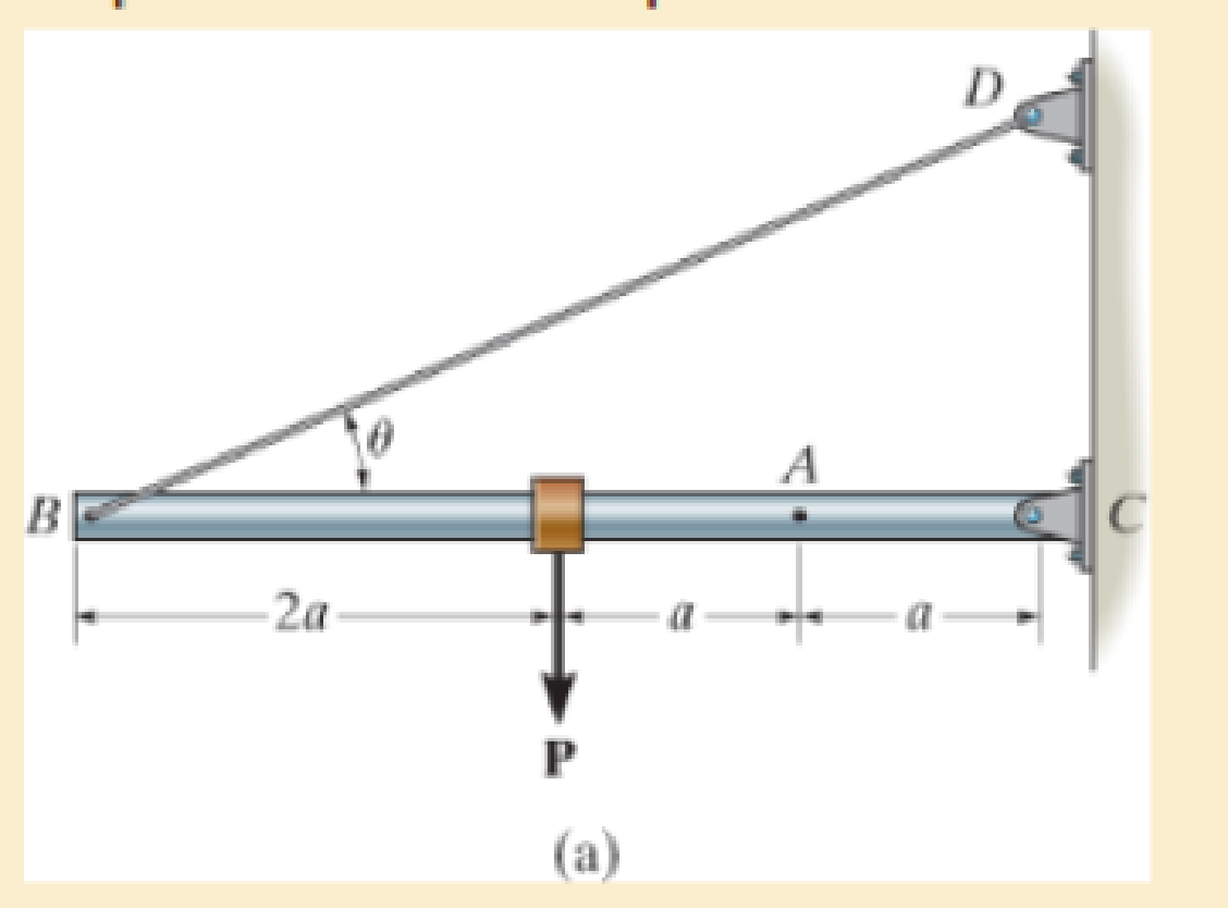
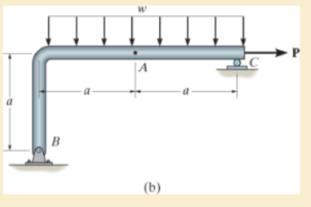
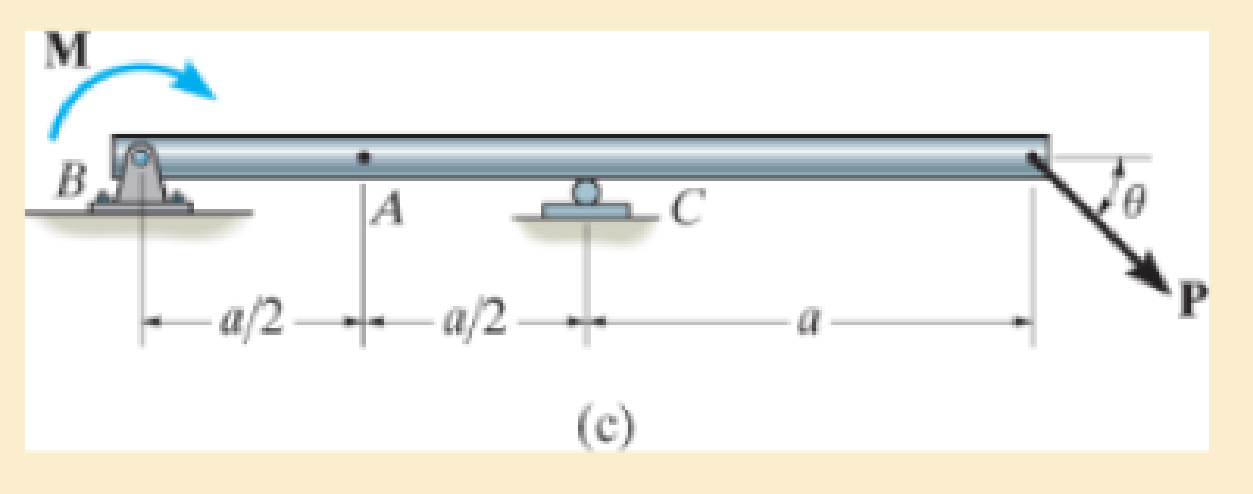
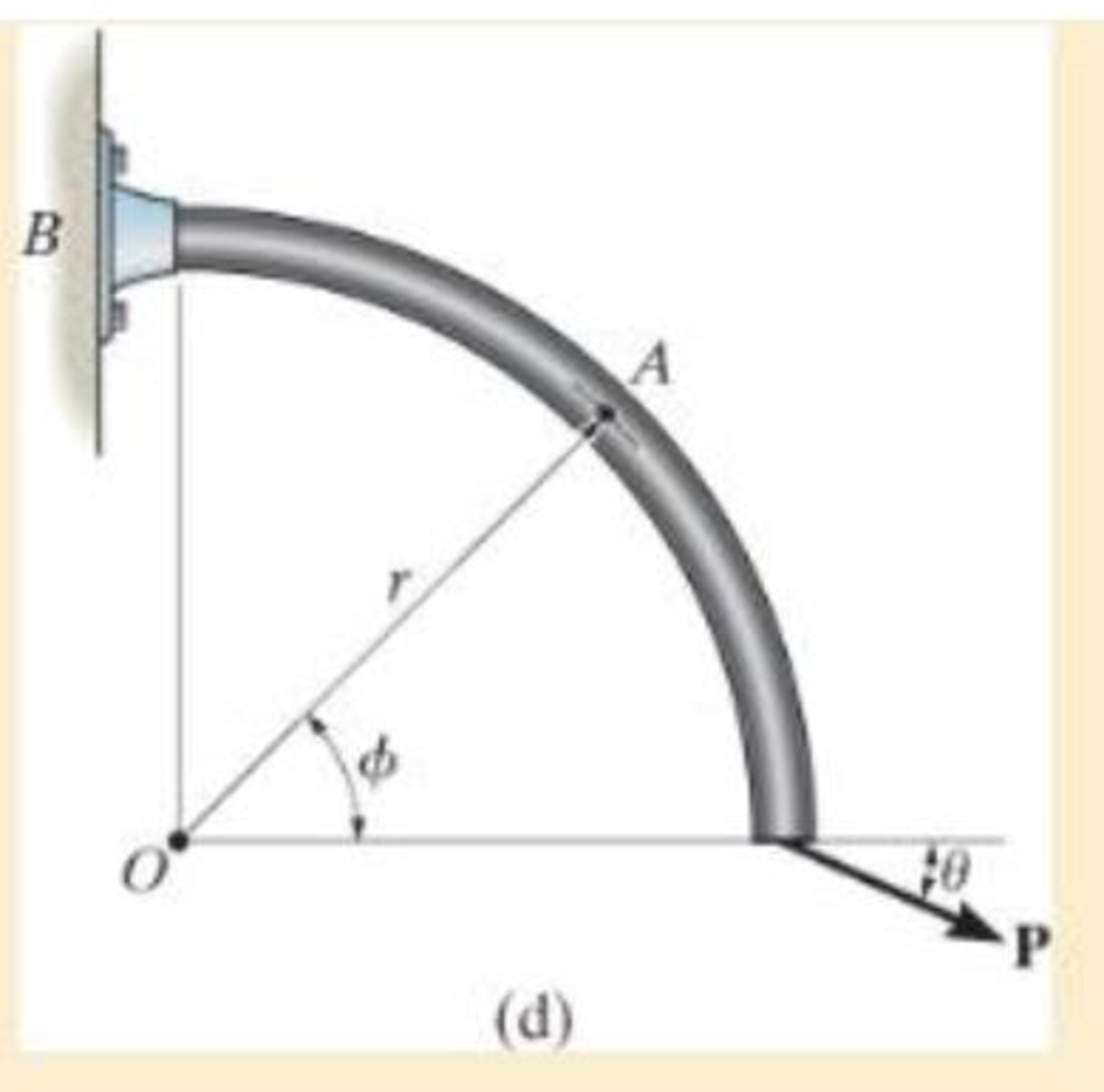
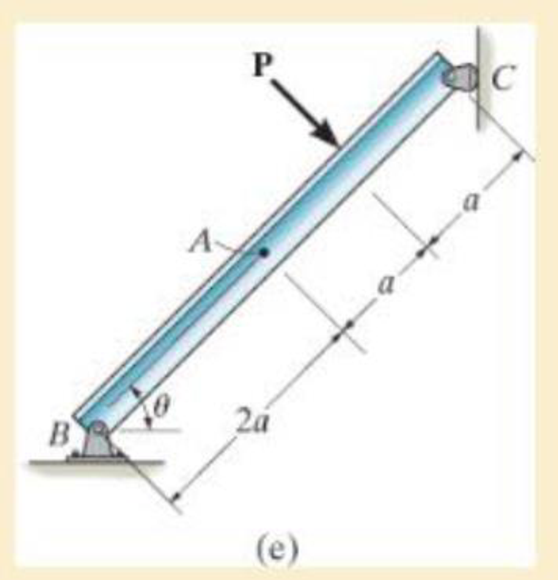
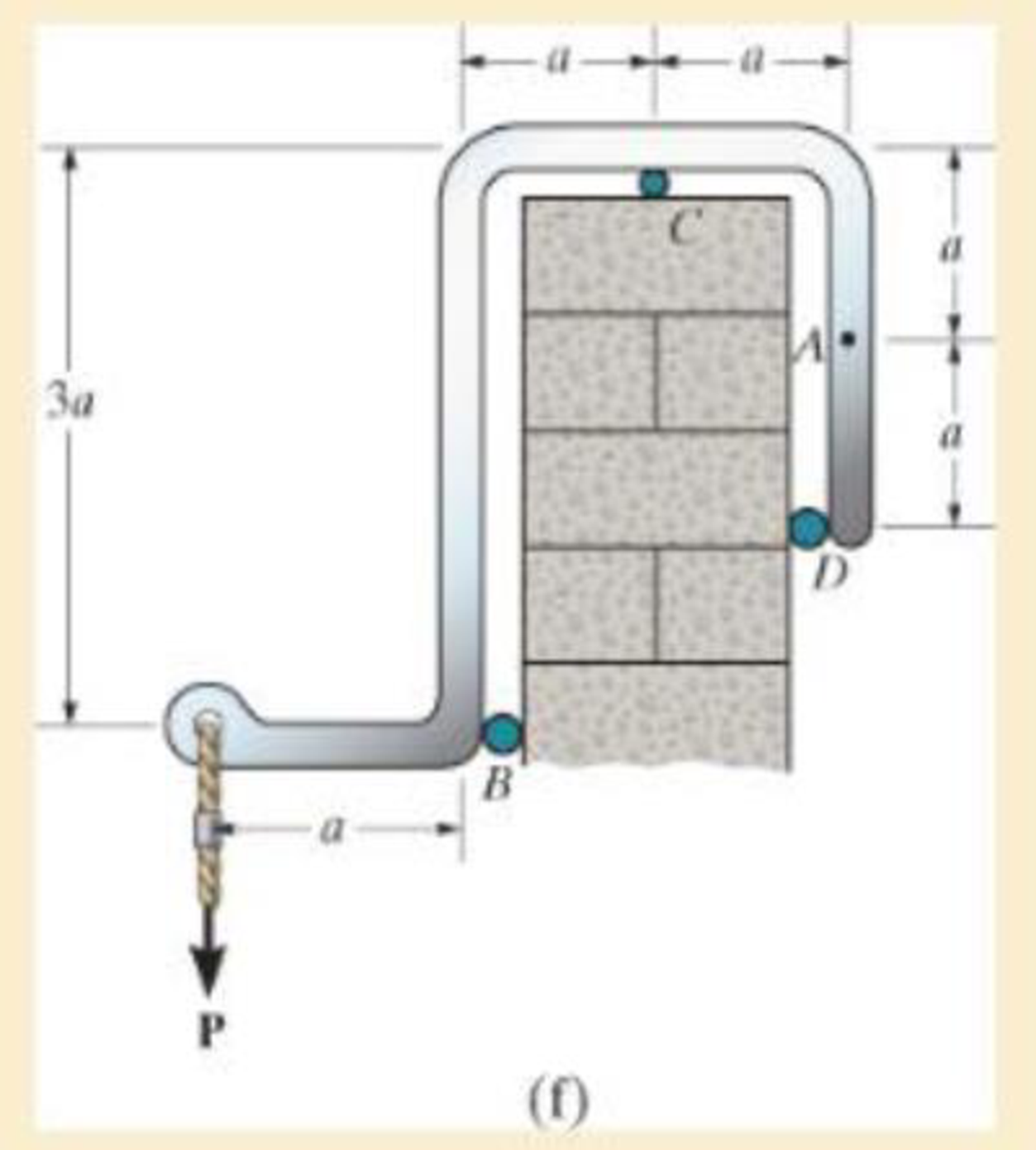
In each case, explain how to find the resultant internal loading acting on the cross section at point A. Draw all necessary free-body diagrams, and indicate the relevant equations of equilibrium. Do not calculate values. The lettered dimensions, angles, and loads are assumed to be known.

Trending nowThis is a popular solution!

Chapter 1 Solutions
Modified Mastering Engineering with Pearson eText -- Standalone Access Card -- for Mechanics of Materials
Additional Engineering Textbook Solutions
Applied Statics and Strength of Materials (6th Edition)
Engineering Mechanics: Statics & Dynamics (14th Edition)
Statics and Mechanics of Materials (5th Edition)
Thinking Like an Engineer: An Active Learning Approach (4th Edition)
INTERNATIONAL EDITION---Engineering Mechanics: Statics, 14th edition (SI unit)
Thinking Like an Engineer: An Active Learning Approach (3rd Edition)


- The bearings at A and D exert only y and z components of force on the shaft as shown in Fig 7. Determine the smallest diameter of the shaft using maximum shear stress hypothesis theory if the allowable stress is 100 MPa.arrow_forwardDetermine the load P if the end C is displaced 0.075 in. downward.arrow_forwardDraw the Free Body Diagram and solve the problemarrow_forward
- In each case, determine the internal normal force between lettered points on the bar. Draw all necessary free-body diagrams.arrow_forwardDetermine the maximum deformation of the bar when subjected to the load systemarrow_forwardThe axle of the freight train is subjected to loadings as shown below. The diameter of the axle is 137.5 mm. If it is supported by two journal bearings at C and D, determine the maximum bending Stress. Include a FBD, SFD and BMD using either the section or graphical method. Draw a cross-section of the shaft and indicate the points of maximum tension and compression.arrow_forward
- The W24 * 104 A-36 steel beam is used to support the uniform distributed load and a concentrated force which is applied at its end. If the force acts at an angle with the vertical as shown, determine the horizontal and vertical displacement at A.arrow_forwardDetermine the shape factor for the member having the tubular cross section.arrow_forwardThe stress–strain diagram for a titanium alloy can be approximated by the two straight lines. If a strut made of this material is subjected to bending, determine the moment resisted by the strut if the maximum stress reaches a value of (a) sA and (b) sB.arrow_forward
- The bar is made of an aluminum alloy having a stress–strain diagram that can be approximated by the straight line segments shown. Assuming that this diagram is the same for both tension and compression, determine the moment the bar will support if the maximum strain at the top and bottom fibers of the beam is Pmax = 0.05.arrow_forwardThe eye hook has the dimensions shown. If it supports a cable loading of 800 lb, determine the maximum normal stress at section a–a and sketch the stress distribution acting over the cross section. Use the curved-beam formula to calculate the bending stress.arrow_forward1–1. The shaft is supported by a smooth thrust bearing at B and a journal bearing at C. Determine the resultant internal loadings acting on the cross section at E. Problem 1–1arrow_forward
 Elements Of ElectromagneticsMechanical EngineeringISBN:9780190698614Author:Sadiku, Matthew N. O.Publisher:Oxford University Press
 Mechanics of Materials (10th Edition)Mechanical EngineeringISBN:9780134319650Author:Russell C. HibbelerPublisher:PEARSON
 Thermodynamics: An Engineering ApproachMechanical EngineeringISBN:9781259822674Author:Yunus A. Cengel Dr., Michael A. BolesPublisher:McGraw-Hill Education
 Control Systems EngineeringMechanical EngineeringISBN:9781118170519Author:Norman S. NisePublisher:WILEY
 Mechanics of Materials (MindTap Course List)Mechanical EngineeringISBN:9781337093347Author:Barry J. Goodno, James M. GerePublisher:Cengage Learning
 Engineering Mechanics: StaticsMechanical EngineeringISBN:9781118807330Author:James L. Meriam, L. G. Kraige, J. N. BoltonPublisher:WILEY