
Applied Statics and Strength of Materials (6th Edition)
6th Edition
ISBN: 9780133840728
Author: Limbrunner
Publisher: PEARSON
expand_more
expand_more
format_list_bulleted
Concept explainers
Videos
Textbook Question
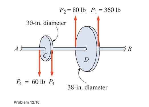
Chapter 12, Problem 12.10P
Pulleys C and D are attached to shaft AB, as shown. The shaft is supported on bearings at each end. The shaft rotates at a uniform speed. Pulley D is the driver and pulley C is the power take-off. The diameter of the shaft is 2
a. the belt tension
b. the maximum shear stress in the shaft.
Expert Solution & Answer
Want to see the full answer?
Check out a sample textbook solution
Students have asked these similar questions
he compound shaft is attached to a rigid wall at each end. For the bronze segment AB, the diameter is 75 mm and G = 35 GPa. For the steel segment BC, the diameter is 50 mm and G = 83 GPa. Given that a = 2 m and b = 1.5 m, compute the largest torque T in kN-m that can be applied as shown in the figure if the maximum shear stress is limited to 60 MPa in the bronze and 80 MPa in the steel.
A flange-and-bolt coupling between two shafts carries 12 bolts at a pitch diameter of 18 in. The shafts carry a torque of 50,000 ft-lb. Assuming that this torque is transmitted by shear across the 12 bolts and that these bolts are to be designed for a shear stress s3 = 3,000 lb/sq in., what is the bolt diameter?
The compound shaft is attached to a rigid wall at each end. For the bronze segment AB, the diameter is 75 mm and G = 35 GPa. For the steel segment BC, the diameter is 50 mm and G = 83 GPa. Given that a = 2 m and b = 1.5 m, compute the largest torque T in kN-m that can be applied as shown in the figure if the maximum shear stress is limited to 60 MPa in the bronze and 80 MPa in the steel. Answer in 2 decimal places
Chapter 12 Solutions
Applied Statics and Strength of Materials (6th Edition)
Ch. 12 - Determine the internal resisting torque in the...Ch. 12 - Determine the internal resisting torque in the...Ch. 12 - Calculate the maximum shear stress developed in a...Ch. 12 - Calculate the allowable torque for a hollow steel...Ch. 12 - Calculate the allowable torque that may be applied...Ch. 12 - A hollow circular steel shaft has a 100-mm outside...Ch. 12 - Design a solid circular steel shaft to transmit an...Ch. 12 - Calculate the shear stresses at the outer and...Ch. 12 - A hollow shaft is produced by boring a...Ch. 12 - Pulleys C and D are attached to shaft AB, as...
Ch. 12 - Calculate the angle of twist a 3-in-diameter...Ch. 12 - Calculate the angle of twist a 65-mm-diameter...Ch. 12 - Calculate the angle of twist a 4-in.-diameter...Ch. 12 - Prob. 12.14PCh. 12 - Prob. 12.15PCh. 12 - A solid steel shaft is to resist a torque of 9000...Ch. 12 - A hollow steel shaft has a 50-mm outside diameter...Ch. 12 - If the shaft of Problem 12.17 were solid, with the...Ch. 12 - An automobile engine develops 90 hp at 3500 rpm....Ch. 12 - Calculate the speed (rpm) at which a...Ch. 12 - Select the diameter of a solid circular steel...Ch. 12 - Select the diameter for a hollow steel shaft that...Ch. 12 - A 6-ft-long solid steel shaft with a diameter of 4...Ch. 12 - The outside and inside diameters of a hollow steel...Ch. 12 - Calculate the maximum shear stress developed in a...Ch. 12 - Write a program that will calculate the allowable...Ch. 12 - Write a program that will generate a table of...Ch. 12 - Rework the program of Problem 12.27 using SI...Ch. 12 - Write a program that will generate a table of...Ch. 12 - Compute the maximum shear stress in the hollow...Ch. 12 - Calculate the allowable torque that may be applied...Ch. 12 - Design a hollow steel shaft to transmit a torque...Ch. 12 - A 32-in.-long solid steel circular shaft, 3 in. in...Ch. 12 - The 65-mm-diameter solid shaft shown is subjected...Ch. 12 - Rework Problem 12.34, changing the diameter of...Ch. 12 - Compute the maximum shear stress in the circular...Ch. 12 - Determine the allowable torque a hollow steel...Ch. 12 - A 1.00-m-long steel wire, 4 mm in diameter, is...Ch. 12 - Select the outside and inside diameters for a...Ch. 12 - A solid aluminum shaft, 6 ft in length, is to...Ch. 12 - A 25-mm-diameter solid shaft with an allowable...Ch. 12 - Compute a. the maximum shear stress developed in a...Ch. 12 - What horsepower can a solid steel shaft 6 in. in...Ch. 12 - Calculate the maximum power that may be...Ch. 12 - A small ski lift has a main cable driving wheel 11...Ch. 12 - A 32-mm-diameter solid shaft transmits 100 kW of...Ch. 12 - A solid steel shaft is to transmit power of 58 kW...Ch. 12 - Select the diameter for a solid steel shaft that...Ch. 12 - A solid steel shaft is to transmit 100 hp at a...Ch. 12 - Two shafts-one a hollow steel shaft with an...Ch. 12 - A 112 -in.-diameter solid steel shaft is 40 ft in...Ch. 12 - A solid steel shaft is to transmit 120 hp. The...
Knowledge Booster


Learn more about
Need a deep-dive on the concept behind this application? Look no further. Learn more about this topic, mechanical-engineering and related others by exploring similar questions and additional content below.Similar questions
- Repeat Problem 11.2-3 assuming that R= 10 kN · m/rad and L = 2 m.arrow_forwardA safety valve on the top of a tank containing steam under pressure p has a discharge hole of diameter d(see figure). The valve is designed to release the steam when the pressure reaches the value Pmax If the natural length of the spring, is L and its stiffness is k, what should be the dimension ft of the valve? (Express your result as a formula for h.)arrow_forwardRepeat Problem 11.3-9. Use two C 150 × 12.2 steel shapes and assume that E = 205 GPa and L = 6 m.arrow_forward
- Two sections of steel drill pipe, joined by bolted flange plates at Ä are being tested to assess the adequacy of both the pipes. In the test, the pipe structure is fixed at A, a concentrated torque of 500 kN - m is applied at x = 0.5 m, and uniformly distributed torque intensity t1= 250 kN m/m is applied on pipe BC. Both pipes have the same inner diameter = 200 mm. Pipe AB has thickness tAB=15 mm, while pipe BC has thickness TBC= 12 mm. Find the maximum shear stress and maximum twist of the pipe and their locations along the pipe. Assume G = 75 GPa.arrow_forwardA circular steel tube of length L = 1.0 m is loaded in torsion by torques T (see figure). (a) If the inner radius of the tube is r1= 45 mm and the measured angle of twist between the ends is 0.5°, what is the shear strain y1(in radians) at the inner surface? (b) If the maximum allowable shear strain is 0.0004 rad and the angle of twist is to be kept at 0.45° by adjusting the torque T, what is the maxi mum permissible outer radius (r2)max?arrow_forwardSolve the preceding problem for the following data: diameter LO m, thickness 48 mm, pressure 22 MPa, modulus 210 GPa. and Poisson's ratio 0.29arrow_forward
- Solve the preceding problem if the length L = 56 in., the inner radius r1— 1.25 in., the angle of twist is 0.5°, and the allowable shear strain is 0.0004 rad.arrow_forwardWhen drilling a hole in a table leg, a furniture maker uses a hand-operated drill (see figure) with a bit of diameter d = 4.0 mm. If the resisting torque supplied by the table leg is equal to 0.3 N · m, what is the maximum shear stress in the drill bit? If the allowable shear stress in the drill bit is 32 MPa, what is the maximum resisting torque before the drill binds up? If the shear modulus of elasticity of the steel is G = 75 GPa, what is the rate of twist of the drill bit (degrees per meter)?arrow_forwardAt a full d raw, an archer applies a pull of 130 N to the bowstring of the bow shown in the figure. Determine the bending moment at the midpoint of the bow.arrow_forward
- A prospector uses a hand-powered winch (see figure) to raise a bucket of ore in his mine shaft. The axle of the winch is a steel rod of diameter d = 0.625 in. Also, the distance from the center of the axle to the center of the lifting rope is b = 4.0 in, If the weight of the loaded bucket is W = 100 lb, what is the maximum shear stress in the axle due to torsion? If the maximum bucket load is 125 lb and the allowable shear stress in the axle is 9250 psi, what is the minimum permissible axle diameter?arrow_forwardSolve the preceding problem if F =90 mm, F = 42 kN, and t = 40°MPaarrow_forwardA plane frame with a pin support at A and roller supports at C and £ has a cable attached at E. which runs over Frictionless pulleys al D and B (see figure). The cable force is known to be 400 N. There is a pin connection just Lo the left of joint C. (a) Find reactions at supports^, C, and E. (b) Find internal stress, resultants N, V, and M just to the right of joint C. (c) Find resultant force in the pin near C.arrow_forward
arrow_back_ios
SEE MORE QUESTIONS
arrow_forward_ios
Recommended textbooks for you
 Mechanics of Materials (MindTap Course List)Mechanical EngineeringISBN:9781337093347Author:Barry J. Goodno, James M. GerePublisher:Cengage Learning
Mechanics of Materials (MindTap Course List)
Mechanical Engineering
ISBN:9781337093347
Author:Barry J. Goodno, James M. Gere
Publisher:Cengage Learning
EVERYTHING on Axial Loading Normal Stress in 10 MINUTES - Mechanics of Materials; Author: Less Boring Lectures;https://www.youtube.com/watch?v=jQ-fNqZWrNg;License: Standard YouTube License, CC-BY