
Videos
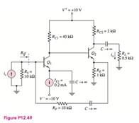
The circuit in Figure P 12.49 has transistor parameters:
the small-signal parameters for
(a)
The value of the small signal parameters for
Answer to Problem 12.49P
Thevalue of small signal resistances are
Explanation of Solution
Given:
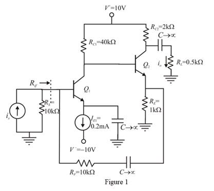
The given diagram is shown in Figure 1
Calculation:
The small signal circuit for the given circuit is shown in Figure 2.
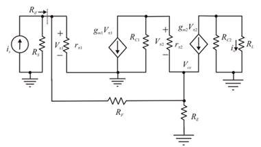
Figure 2
The expression to determine the value of the current
Substitute
The expression to determine the value of the voltage
Substitute
The value of the current
Substitute
The expression to determine the value of the current
Substitute
The expression for the small signal input resistance is given by,
Substitute
The expression for the trans-conductance of the first transistor is given by,
Substitute
The expression for the small signal input resistance is given by,
Substitute
The expression for the trans-conductance of the first transistor is given by,
Substitute
Conclusion:
Therefore, the value of small signal resistances are
(b)
The value of small signal closed loop current gain.
Answer to Problem 12.49P
The value of the small signal closed loop current gain is
Explanation of Solution
Given:
The given diagram is shown in Figure 1

Calculation:
Apply KCL at the source.
Substitute
Consider the KCL equation.
Substitute
Apply KCL at
Substitute
Substitute
Substitute
Substitute
The expression to determine the value of the output current is given by,
Substitute
Substitute
Conclusion:
Therefore, the value of the small signal closed loop current gain is
(c)
The value of the resistance
Answer to Problem 12.49P
The value of the resistance is
Explanation of Solution
Given:
The given diagram is shown in Figure 1

Calculation:
Substitute
The expression to determine the value of the input resistance is given by,
Substitute
The expression to determine the value of the input feedback resistance is given by,
Substitute
Conclusion:
Therefore, the value of the resistance is
Want to see more full solutions like this?
Chapter 12 Solutions
MICROELECT. CIRCUIT ANALYSIS&DESIGN (LL)


- Discuss the difference between the current series negative feedback amplifier and voltage shunt feedback amplifier in terms of output impedance, input impedance, voltage gain, bandwidth, distortion and noise.arrow_forwarddescribe the expression of sensitivity of C.L.T.F. wrt. feedback gain.arrow_forwardA unity feedback system with open-loop transfer function given as:?(?) = ??. ?(? + ?)(? + ?)(? + ??)without affecting its operating point (−1.54 ∓ ??2.66) appreciably a- Design a suitable compensator to drive the step response error to zero.b- Design a suitable compensator to reduce step error by factor of 5.arrow_forward
- Find the range of K using the Routh - Hurwitz method for the closed - loop stability of the negative unit feedback system given the open - loop transition function belowarrow_forwardConsider a system with an open loop transfer function defined by Determine the expression of the phase advance corrector that must be used to have a phase margin greater than 40º while limiting the static error in position to 1/6.arrow_forwardCalculate the feedback gain AF value. RİF=? ROF=?arrow_forward
- Determine,if it exists,a state feedback gain K such that the closed loop poles are located at −5 and −6.arrow_forwardAn inverting amplifier is to be designed with a gain of 5 and an input impedance of 10k ohms. What should be the value of the feedback resistance?arrow_forwardThe input-output transfer function of the system shown in Figure 1 is used with the help of Mason gain formulation. specifyarrow_forward
 Introductory Circuit Analysis (13th Edition)Electrical EngineeringISBN:9780133923605Author:Robert L. BoylestadPublisher:PEARSON
 Delmar's Standard Textbook Of ElectricityElectrical EngineeringISBN:9781337900348Author:Stephen L. HermanPublisher:Cengage Learning
 Programmable Logic ControllersElectrical EngineeringISBN:9780073373843Author:Frank D. PetruzellaPublisher:McGraw-Hill Education
 Fundamentals of Electric CircuitsElectrical EngineeringISBN:9780078028229Author:Charles K Alexander, Matthew SadikuPublisher:McGraw-Hill Education
 Electric Circuits. (11th Edition)Electrical EngineeringISBN:9780134746968Author:James W. Nilsson, Susan RiedelPublisher:PEARSON
 Engineering ElectromagneticsElectrical EngineeringISBN:9780078028151Author:Hayt, William H. (william Hart), Jr, BUCK, John A.Publisher:Mcgraw-hill Education,