
Introductory Circuit Analysis (13th Edition)
13th Edition
ISBN: 9780133923605
Author: Robert L. Boylestad
Publisher: PEARSON
expand_more
expand_more
format_list_bulleted
Concept explainers
Videos
Textbook Question
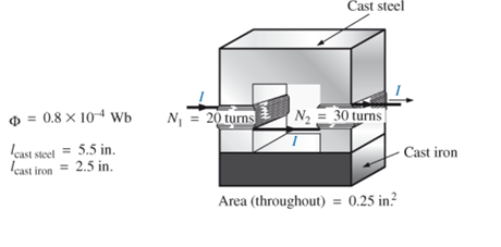
Chapter 12, Problem 13P
For the series magnetic circuit in Fig.12.40 with two impressed sources of magnetic “pressure,” determine the current I. Each applied mmf establishes a flux pattern in the clockwise direction.
Expert Solution & Answer
Want to see the full answer?
Check out a sample textbook solution
Students have asked these similar questions
21
In a DC generator, if the core loss constant and the copper loss is increasing, then the efficiency will be maximum.
Select one:
True
False
The emf per turn of a single phase 10 kVA, 2200/220V, 50 Hz transformer is 10V. Calculate the net cross-sectional area of core for a maximum flux density of 1.5T. Note: flux (Weber) = BA where B = flux density (Tesla) and A is area (m²)
Find the no load line voltage of a star connected 4-pole alternator form the following: Flux per pole = 0.12 Wb, Slots per pole per phase = 4, Conductors/slot = 6, Two layer winding with coil span = 150°
Chapter 12 Solutions
Introductory Circuit Analysis (13th Edition)
Ch. 12 - Using Appendix E, fill in the blanks in the...Ch. 12 - Repeat Problem 1 for the following table if...Ch. 12 - For the electromagnet in Fig. 12.34 a. Find the...Ch. 12 - Which section of Fig. 12.35-(a), (b), or (c)-has...Ch. 12 - Find the reluctance of a magnetic circuit if a...Ch. 12 - Prob. 6PCh. 12 - Find the magnetizing force H for Problem 5 in SI...Ch. 12 - If a magnetizing force H of 600 At/m is applied to...Ch. 12 - For the series magnetic circuit in Fig. 12.36,...Ch. 12 - Find the current necessary to establish a flux of...
Ch. 12 - a. Find the number of turns N1 required to...Ch. 12 - a. Find the mmf (NI) required to establish a flux...Ch. 12 - For the series magnetic circuit in Fig.12.40 with...Ch. 12 - a. Find the current I required to establish a flux...Ch. 12 - Prob. 15PCh. 12 - Determine the current I1 required to establsh a...Ch. 12 - a. A flux of 0.210-4Wb will establish sufficient...Ch. 12 - For the series-parallel magnetic circuit in Fig....Ch. 12 - Find the magnetic flux established in the series...Ch. 12 - Prob. 20PCh. 12 - Note how closely the B-H curve of cast steel in...
Knowledge Booster


Learn more about
Need a deep-dive on the concept behind this application? Look no further. Learn more about this topic, electrical-engineering and related others by exploring similar questions and additional content below.Similar questions
- A single-phase, 120V(rms),60Hz source supplies power to a series R-L circuit consisting of R=10 and L=40mH. (a) Determine the power factor of the circuit and state whether it is lagging or leading. (b) Determine the real and reactive power absorbed by the load. (c) Calculate the peak magnetic energy Wint stored in the inductor by using the expression Wint=L(Irms)2 and check whether the reactive power Q=Wint is satisfied. (Note: The instantaneous magnetic energy storage fluctuates between zero and the peak energy. This energy must be sent twice each cycle to the load from the source by means of reactive power flows.)arrow_forwardAn 8-pole lap-wound d.c. generator has 120 slots having 4 conductors perslot. If each conductor can carry 250 A and if flux/pole is 0.05 Wb,calculate the speed of the generator for giving 240 V on open circuit. Ifthe voltage drops to 220 V on full load, find the rated output of themachine.arrow_forwardIn a pair of coupled coils, coil 1 has a continuous of 2 A and the corresponding fluxes φ11 and φ21 are 0.3 and 0.6 mWb respectively. If the turns are N1= 500, N2= 500, find L1, L2, M and K.arrow_forward
- 8. A 3-phase, 50 Hz transformer has an iron cross section of 400 cm^2. If the flux density be limited to 1.2 T, find the number of turns per phase on high and low voltage windings. The voltage ratio is 2,200/110 V, the HV side being connected in wye and the LV side is delta.arrow_forwardA 50 Hz, 2 pole, 3Φ star-connected turbo alternator has 54 slots with 4 conductors per slot. The pitch of the coils is 2 slots less than the pole pitch. If the machine gives 3300 V between lines on open circuit sinusoidal flux distribution, determine the useful flux per pole.arrow_forwardc) Compute the no load line voltage of a star connected 4-pole alternator for the following data:• Flux per pole = 0.12 weber• Slots per pole per phase =4• Conductors/slot = 4• Two layer winding, with coil span = 1500arrow_forward
- The electrodynamic wattmeter consist of two fixed coils ‘a’ and ‘b’ placed unsymmetrical to each other and producing a uniform magnetic field نقطة واحدة True Falsearrow_forwardCalculate the speed and open-circuit line and phase voltages of a 4-pole, 3-phase, 50Hz, star connected alternator with 36 slots and 30 conductors per slot. The flux per pole is 0.0496 Wb and is sinusoidally distributed.arrow_forwardThe insulation resistance of a single-core cable is 432 Mohm per km. If the core diameter is 2.87 cm and resistivity of insulation is 5.1 x 10^14 ohm-cm, find the insulation thickness.arrow_forward
- Calculate the core area in Cm 2 required for a 1600kVA, 6600/440 V, 50Hz single phasetransformer. Assume maximum flux density of 1.2 Wb/m 2 and induced voltage per turn 0f30Varrow_forwardAn DC series generator is otherwise called it as variable flux machine. Select one: True Falsearrow_forwardA 4-pole, 3-phase, 50-Hz, star-connected alternator has 60 slots, with 4 conductors per slot. Coils are short-pitched by 3 slots. If the phase spread is 60º, find the line voltage induced for a flux per pole of 0.943 Wb distributed sinusoidally in space. All the turns per phase is in series.arrow_forward
arrow_back_ios
SEE MORE QUESTIONS
arrow_forward_ios
Recommended textbooks for you
 Power System Analysis and Design (MindTap Course ...Electrical EngineeringISBN:9781305632134Author:J. Duncan Glover, Thomas Overbye, Mulukutla S. SarmaPublisher:Cengage Learning
Power System Analysis and Design (MindTap Course ...
Electrical Engineering
ISBN:9781305632134
Author:J. Duncan Glover, Thomas Overbye, Mulukutla S. Sarma
Publisher:Cengage Learning
Fault Analysis in Power Systems part 1a; Author: GeneralPAC: Power System Tutorials;https://www.youtube.com/watch?v=g8itg4MOjok;License: Standard youtube license