
Electronics Fundamentals: Circuits, Devices & Applications
8th Edition
ISBN: 9780135072950
Author: Thomas L. Floyd, David Buchla
Publisher: Prentice Hall
expand_more
expand_more
format_list_bulleted
Videos
Textbook Question
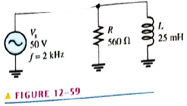
Chapter 12, Problem 21P
Determine the following quantities in Figure 12-59:
Expert Solution & Answer
Want to see the full answer?
Check out a sample textbook solution
Students have asked these similar questions
11 - In the series R-L circuit, AA 12 V with a frequency of 50 Hz is applied to the ends of the coil with a resistance of 10 Ω and an inductance of 20 mH.Which of the following is the phase difference (power factor) between the current passing through the circuit and the voltage?A) 0.42B) 0.21C) 0.5D) 0.84E) 0.45
Determine the current in the circuit if inductance is equals to 1 H
Answer: i = 0.25 sin(120t-90o) A
Determine the current in the circuit if inductance is equals to 10 mH
Answer: i = 5.31 sin(377t-90o) A
Chapter 12 Solutions
Electronics Fundamentals: Circuits, Devices & Applications
Ch. 12 - In an ac circuit where R=XL, the phase angle is...Ch. 12 - Prob. 2TFQCh. 12 - In an ac series RL circuit, the current and...Ch. 12 - In an ac parallel RL circuit, the inductive...Ch. 12 - In an ac parallel RL circuit, the voltage across...Ch. 12 - The unit siemens is used to measure both...Ch. 12 - Prob. 7TFQCh. 12 - If the power factor of a circuit is 0.5, the...Ch. 12 - Prob. 9TFQCh. 12 - Prob. 10TFQ
Ch. 12 - In a series RL circuit, the resistor voltage Leads...Ch. 12 - Prob. 2STCh. 12 - Prob. 3STCh. 12 - If the frequency is doubled and the resistance is...Ch. 12 - Prob. 5STCh. 12 - Prob. 6STCh. 12 - Prob. 7STCh. 12 - Prob. 8STCh. 12 - Prob. 9STCh. 12 - Prob. 10STCh. 12 - Prob. 11STCh. 12 - Prob. 12STCh. 12 - If a load is purely inductive and the reactive...Ch. 12 - Prob. 14STCh. 12 - Prob. 15STCh. 12 - Determine the cause for each set of symptoms....Ch. 12 - Determine the cause for each set of symptoms....Ch. 12 - Prob. 3TSCCh. 12 - Prob. 4TSCCh. 12 - Prob. 5TSCCh. 12 - Prob. 1PCh. 12 - Prob. 2PCh. 12 - Find the impedance of each circuit in Figure...Ch. 12 - Determine the impedance and phase angle in each...Ch. 12 - In Figure 12-52, determine the impedance at each...Ch. 12 - Determine the values of R and XL in a series RL...Ch. 12 - If the frequency of the source is increased to 1...Ch. 12 - Determine the voltage across the total resistance...Ch. 12 - Find the current for each circuit of Figure 12-50.Ch. 12 - Calculate the total current in each circuit of...Ch. 12 - Determine for the cicutit in Figure 12-53.Ch. 12 - If the inductance in Figure 12-53 is doubled, does...Ch. 12 - Draw the waveforms for Vs,VRandVL in Figure 12-53....Ch. 12 - For the circuit in Figure 12-54, find VRandVL for...Ch. 12 - For the lag circuit in Figure 12-55, determine the...Ch. 12 - Repeat Problem 15 for the lead circuit in Figure...Ch. 12 - What is the impedance for the circuit in Figure...Ch. 12 - Repeat Problem 17 for the following frequencies:...Ch. 12 - At what frequecy does XL equal R in Figure 12-57?Ch. 12 - Find the total current and each branch current in...Ch. 12 - Determine the following quantities in Figure...Ch. 12 - Convert the circuit in Figure 12-60 to an...Ch. 12 - Determine the voltage across each element in...Ch. 12 - Is the circuit in Figure 12-61 predominantly...Ch. 12 - Find the current in each branch and the total...Ch. 12 - In a certain RL circuit, the true power is 100 mW,...Ch. 12 - Determine the true power and the reactive power in...Ch. 12 - What is the power factor in Figure 12-58?Ch. 12 - Determine Ptrue,Pr,Pa, and PF for the circuit in...Ch. 12 - Plot the response curve for the circuit in Figure...Ch. 12 - Using the same procedure as in Problem 30, plot...Ch. 12 - Draw the voltage phasor diagram for each circuit...Ch. 12 - Prob. 33PCh. 12 - Prob. 34PCh. 12 - Determine the voltage across the inductors in...Ch. 12 - Is the circuit in Figure 12-64 predominantly...Ch. 12 - Find the total current in Figure 12-64.Ch. 12 - Determine the phase shift and attenuation...Ch. 12 - Design an ideal inductive switching circuit that...Ch. 12 - Prob. 44PCh. 12 - Prob. 45PCh. 12 - Prob. 46PCh. 12 - Prob. 47PCh. 12 - Open file P12-48. Determine if there is a fault...Ch. 12 - Prob. 49P
Knowledge Booster


Learn more about
Need a deep-dive on the concept behind this application? Look no further. Learn more about this topic, electrical-engineering and related others by exploring similar questions and additional content below.Similar questions
- The circuit in Figure 24-2 is connected to a 1000-Hz line. The resistor has a current flow of 60 A, the inductor has a current flow of 150 A, and the capacitor has a current flow of 70 A. The circuit has a total impedance of 4.8 . ETITZ4.8VAPFERIR60ARPELIL150AXLVARsLLECIC150AXCVARsCCarrow_forwardThe circuit in Figure 24-2 is connected to a 120-V, 60-Hz line. The resistor has a resistance of 36 , the inductor has an inductive reactance of 40 , and the capacitor has a capacitive reactance of 50 . ET120VITZVAPFERIRR36PELILXL40VARsLLECICXC50VARsCCarrow_forwardThe circuit is connected to a 400-Hz line with an applied voltage of 35.678 V. The resistor has a true power of 14.4 W. and there are 12.96 inductive VARs and 28.8 capacitive VARs. ET35.678VITZVAPFERIRRP14.4WELILXLVARsL12.96LECICXCVARsC28.8Carrow_forward
- Assume the circuit shown in Figure 21-1 has an apparent power of 432 VA and a true power of 345.6 W. The capacitor has a capacitance of 15.8919 F, and the frequency is 60 Hz. Find the missing values. ET ER EC IT IR IC Z R XC VA432 P345.6W VARSC PF C15.8919Farrow_forwardIn an R-L series circuit, the apparent power is 560 VA, PF = 62%. Find reactive power.arrow_forwardAn AC series ciruit has an apparent power of 650 VA, and a true power of 475 watts. what is the reactive power in the circuit?arrow_forward
- A resistor of 200 Ω, a coil with reactance 200 Ω and a capacitor with reactance 300 Ω are connected in series.What is the value of the impedance?A. 200 + j100. C. 200 - j200.B. 200 - j200. D. 200 - j100arrow_forwardWhat is the value of the total capacitive reactance in each circuit in figure 12-81?arrow_forwardTwo inductive impedance A and B are connected in series. A has R = 5 Ω, L = 0.01 H; B has R = 3 Ω , L = 0.02 H. If a sinusoidal voltage of 230 V at 50 Hz is applied to the whole circuit calculate the current..arrow_forward
- If, in one (3600), all of the instantaneous power falls under positive loops (no negative loops), the load must be:a. A resistorb. An inductor or capacitorExplain:arrow_forwardIn a pure inductive load, (without resistive elements), the apparent power is a) Equal to the real power b) Greater than the reactive power c) Equal to the reactive power d) None of the abovearrow_forwardANSWER 12-15arrow_forward
arrow_back_ios
SEE MORE QUESTIONS
arrow_forward_ios
Recommended textbooks for you
 Delmar's Standard Textbook Of ElectricityElectrical EngineeringISBN:9781337900348Author:Stephen L. HermanPublisher:Cengage Learning
 Electricity for Refrigeration, Heating, and Air C...Mechanical EngineeringISBN:9781337399128Author:Russell E. SmithPublisher:Cengage Learning
Delmar's Standard Textbook Of Electricity
Electrical Engineering
ISBN:9781337900348
Author:Stephen L. Herman
Publisher:Cengage Learning
Electricity for Refrigeration, Heating, and Air C...
Mechanical Engineering
ISBN:9781337399128
Author:Russell E. Smith
Publisher:Cengage Learning
02 - Sinusoidal AC Voltage Sources in Circuits, Part 1; Author: Math and Science;https://www.youtube.com/watch?v=8zMiIHVMfaw;License: Standard Youtube License