
Electronics Fundamentals: Circuits, Devices & Applications
8th Edition
ISBN: 9780135072950
Author: Thomas L. Floyd, David Buchla
Publisher: Prentice Hall
expand_more
expand_more
format_list_bulleted
Videos
Textbook Question
Chapter 12, Problem 24P
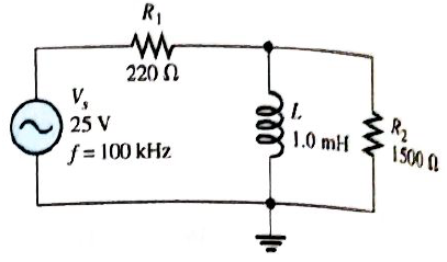
Is the circuit in Figure 12-61 predominantly resistive or predominatly inductive?
Expert Solution & Answer
Want to see the full answer?
Check out a sample textbook solution
Students have asked these similar questions
What is the value of the total capacitive reactance in each circuit in figure 12-81?
What will be magnitude of the total circuit impedance of a series LR circuit excited by a 100 Hz ac source? The resistance is 40 ohm and the inductance is 4 mF.
How did We get the e=12∠-56.897° V
Please explain to me.
Chapter 12 Solutions
Electronics Fundamentals: Circuits, Devices & Applications
Ch. 12 - In an ac circuit where R=XL, the phase angle is...Ch. 12 - Prob. 2TFQCh. 12 - In an ac series RL circuit, the current and...Ch. 12 - In an ac parallel RL circuit, the inductive...Ch. 12 - In an ac parallel RL circuit, the voltage across...Ch. 12 - The unit siemens is used to measure both...Ch. 12 - Prob. 7TFQCh. 12 - If the power factor of a circuit is 0.5, the...Ch. 12 - Prob. 9TFQCh. 12 - Prob. 10TFQ
Ch. 12 - In a series RL circuit, the resistor voltage Leads...Ch. 12 - Prob. 2STCh. 12 - Prob. 3STCh. 12 - If the frequency is doubled and the resistance is...Ch. 12 - Prob. 5STCh. 12 - Prob. 6STCh. 12 - Prob. 7STCh. 12 - Prob. 8STCh. 12 - Prob. 9STCh. 12 - Prob. 10STCh. 12 - Prob. 11STCh. 12 - Prob. 12STCh. 12 - If a load is purely inductive and the reactive...Ch. 12 - Prob. 14STCh. 12 - Prob. 15STCh. 12 - Determine the cause for each set of symptoms....Ch. 12 - Determine the cause for each set of symptoms....Ch. 12 - Prob. 3TSCCh. 12 - Prob. 4TSCCh. 12 - Prob. 5TSCCh. 12 - Prob. 1PCh. 12 - Prob. 2PCh. 12 - Find the impedance of each circuit in Figure...Ch. 12 - Determine the impedance and phase angle in each...Ch. 12 - In Figure 12-52, determine the impedance at each...Ch. 12 - Determine the values of R and XL in a series RL...Ch. 12 - If the frequency of the source is increased to 1...Ch. 12 - Determine the voltage across the total resistance...Ch. 12 - Find the current for each circuit of Figure 12-50.Ch. 12 - Calculate the total current in each circuit of...Ch. 12 - Determine for the cicutit in Figure 12-53.Ch. 12 - If the inductance in Figure 12-53 is doubled, does...Ch. 12 - Draw the waveforms for Vs,VRandVL in Figure 12-53....Ch. 12 - For the circuit in Figure 12-54, find VRandVL for...Ch. 12 - For the lag circuit in Figure 12-55, determine the...Ch. 12 - Repeat Problem 15 for the lead circuit in Figure...Ch. 12 - What is the impedance for the circuit in Figure...Ch. 12 - Repeat Problem 17 for the following frequencies:...Ch. 12 - At what frequecy does XL equal R in Figure 12-57?Ch. 12 - Find the total current and each branch current in...Ch. 12 - Determine the following quantities in Figure...Ch. 12 - Convert the circuit in Figure 12-60 to an...Ch. 12 - Determine the voltage across each element in...Ch. 12 - Is the circuit in Figure 12-61 predominantly...Ch. 12 - Find the current in each branch and the total...Ch. 12 - In a certain RL circuit, the true power is 100 mW,...Ch. 12 - Determine the true power and the reactive power in...Ch. 12 - What is the power factor in Figure 12-58?Ch. 12 - Determine Ptrue,Pr,Pa, and PF for the circuit in...Ch. 12 - Plot the response curve for the circuit in Figure...Ch. 12 - Using the same procedure as in Problem 30, plot...Ch. 12 - Draw the voltage phasor diagram for each circuit...Ch. 12 - Prob. 33PCh. 12 - Prob. 34PCh. 12 - Determine the voltage across the inductors in...Ch. 12 - Is the circuit in Figure 12-64 predominantly...Ch. 12 - Find the total current in Figure 12-64.Ch. 12 - Determine the phase shift and attenuation...Ch. 12 - Design an ideal inductive switching circuit that...Ch. 12 - Prob. 44PCh. 12 - Prob. 45PCh. 12 - Prob. 46PCh. 12 - Prob. 47PCh. 12 - Open file P12-48. Determine if there is a fault...Ch. 12 - Prob. 49P
Knowledge Booster


Learn more about
Need a deep-dive on the concept behind this application? Look no further. Learn more about this topic, electrical-engineering and related others by exploring similar questions and additional content below.Similar questions
- The circuit in Figure 24-2 is connected to a 1000-Hz line. The resistor has a current flow of 60 A, the inductor has a current flow of 150 A, and the capacitor has a current flow of 70 A. The circuit has a total impedance of 4.8 . ETITZ4.8VAPFERIR60ARPELIL150AXLVARsLLECIC150AXCVARsCCarrow_forwardThe circuit in Figure 24-2 is connected to a 120-V, 60-Hz line. The resistor has a resistance of 36 , the inductor has an inductive reactance of 40 , and the capacitor has a capacitive reactance of 50 . ET120VITZVAPFERIRR36PELILXL40VARsLLECICXC50VARsCCarrow_forwardAssume the circuit shown in Figure 21-1 has an apparent power of 432 VA and a true power of 345.6 W. The capacitor has a capacitance of 15.8919 F, and the frequency is 60 Hz. Find the missing values. ET ER EC IT IR IC Z R XC VA432 P345.6W VARSC PF C15.8919Farrow_forward
- Calculate circuit values below. Does the cuicuit change from a lead circuit to a lag circuit as the frequency increases from 500 HZ to 50 Khz?arrow_forwardA resistor of 200 Ω, a coil with reactance 200 Ω and a capacitor with reactance 300 Ω are connected in series.What is the value of the impedance?A. 200 + j100. C. 200 - j200.B. 200 - j200. D. 200 - j100arrow_forwardWhat is the capacitor that must be added to this circuit to get a power factor of .90 The answer key: 21.879microF Can you please break down the answer in steps. Thank youarrow_forward
- True power can be determined by measuring voltage and current in a. R-L series circuit b. Purely resistive ac circuit c. Purely capacitive circuit d. Purely inductive circuitarrow_forwardA 16 Voltage is applied to the circuit with a 47 ohms resistor connected in series with a 10uF capacitor. How much voltage will appear across the capacitor and resistor at a frequency of 500Hz?arrow_forwardIn which circuit current lags the voltage by an angle less than 90 degree a. Purely inductive b. R-L series circuit c. R-C series circuit d. Purely capacitivearrow_forward
- A series resistive capacitive circuit contains 2 resistor and 2 capacitors. The resistors are 39 and 56 The capacitors have a capacitive reactance of 80 and 40 What is the total impedance ?arrow_forward3. A coil has an impedance of 75.4 when connected a across a source of 60 Hz. The same coil yields an impedance of 54.8 when connected across a source having a different frequency of 30 Hz. What is the coil's inductance?arrow_forwardWhat should be the limit of SWR? a. 0arrow_forward
arrow_back_ios
SEE MORE QUESTIONS
arrow_forward_ios
Recommended textbooks for you
 Delmar's Standard Textbook Of ElectricityElectrical EngineeringISBN:9781337900348Author:Stephen L. HermanPublisher:Cengage Learning
Delmar's Standard Textbook Of Electricity
Electrical Engineering
ISBN:9781337900348
Author:Stephen L. Herman
Publisher:Cengage Learning
Inductors Explained - The basics how inductors work working principle; Author: The Engineering Mindset;https://www.youtube.com/watch?v=KSylo01n5FY;License: Standard Youtube License