
Machine Elements in Mechanical Design (6th Edition) (What's New in Trades & Technology)
6th Edition
ISBN: 9780134441184
Author: Robert L. Mott, Edward M. Vavrek, Jyhwen Wang
Publisher: PEARSON
expand_more
expand_more
format_list_bulleted
Concept explainers
Videos
Textbook Question
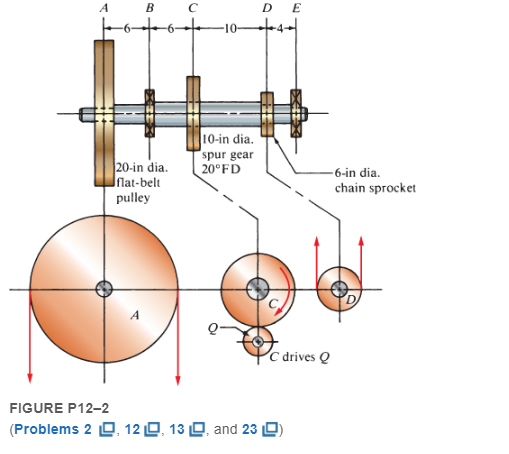
Chapter 12, Problem 2P
See Figure P12−2. The shaft rotating at 200 rpm carries a spur gear C having 80 teeth with a diametral pitch of 8. The teeth are of the 20°, full-depth, involute form. The gear delivers 6 hp to a pinion directly below it. Compute the torque delivered by the shaft to gear C and the tangential and radial forces exerted on the shaft by the gear.
Expert Solution & Answer
Want to see the full answer?
Check out a sample textbook solution
Students have asked these similar questions
Shaft a in the figure has a power input of 75 kW at a speed of 1000 rev/min in the counterclockwise direction. The gears have a module of 5 mm and a 20° pressure angle. Gear 3 is an idler
(b) Find the torque T4c that gear 4 exerts on shaft c.
Shaft a in the figure has a power input of 75 kW at a speed of 1000 rev/min in the counterclock-wise direction. The gears have a module of 5 mm and a 20° pressure angle. Gear 3 is an idler.(a) Find the force F3b that gear 3 exerts against shaft b.(b) Find the torque T4c that gear 4 exerts on shaft c.
The figure shows a pair of shaft-mounted spur
gears having a module of 5 mm with an 18-tooth
20° pressure angle pinion driving a 45-tooth gear.
The power input is 24 kW at 1800 rev/min
counterclockwise into the pinion. Find the
direction and magnitude of the forces acting on
the shafts a and b.
SOLUTION:
Chapter 12 Solutions
Machine Elements in Mechanical Design (6th Edition) (What's New in Trades & Technology)
Knowledge Booster


Learn more about
Need a deep-dive on the concept behind this application? Look no further. Learn more about this topic, mechanical-engineering and related others by exploring similar questions and additional content below.Similar questions
- a in the figure has a power input of 75 kW at a speed of 1000 rev/min in the counterclock- wise direction. The gears have a module of 5 mm and a 20° pressure angle. Gear 3 is an idler. (a) Find the force F3b that gear 3 exerts against shaft b. (b) Find the torque T4c that gear 4 exerts on shaftarrow_forward= Q.3: Calculate the power that can be transmitted safely by a pair of spur gears with the data given below and calculate also, the bending stresses induced in the two wheels when the pair transmits this power. Number of teeth in the pinion 20, Number of teeth in the gear = 80, Module = 4 mm, and Width of teeth = 60 mm, Tooth profile involute, Allowable bending strength of the material;( 200 MPa, for = 400 r.p.m and pinion) and (160 MPa, for gear), Speed of the pinion Service factor = 0.8. = 20° Q.4: Design a wire rope for an elevator (Miscellaneous hoists) in a building of (60 m) height, for a total load (20 kN). The speed of the elevator is (240 m/min) and the full speed is reached at (10 sec). Taken the grade wire is (110), the safety factor is 2.5 and Er =84 x 103 N/mm².arrow_forwardA gear train with a ratio of -6:1 and a diametral pitch of 8 is used to reduce the speed from an electric motor to a shaft driving a grocery checkout conveyor. Grocery checkout conveyor Electric motor @, = 1800 rpm a. If the motor rotates at 1800 rpm clockwise, determine the speed and direction of the large gear. b. For a pressure angle of 20 deg, determine the minimum number of teeth for the pinion. Assume the gears are cut by a shaper (NOT a hob). c. Specify pitch diameters and numbers of teeth for the pinion and the gear for the most compact gear train.arrow_forward
- A pinion having 40 teeth drives a gear having 80 teeth. the profile of the gear is involute with pressure angle ( 22), 12 mm module and (14) mm addendum. Find 1-the length of contact2-Arc of contact 3-Contact ratioarrow_forwardA pair of helical gears are machined with a hob. The hob has a 20 degree pressure angle and machines circular pitch of 0.55 inch/tooth on a spur gear. Two gears are machined, the pinion has 18 teeth and the gear has 36 teeth. The measured transverse diametral pitch on the pinion is 5 inch/tooth. The pinion transmits 10 hp at 1,795 rpm. Calculate the pinion axial force in lbf.arrow_forward4. A pair of spur gears with a centre distance of 495 mm is used for a speed reduction of 4.5:1. The module is 6 mm. Calculate the number of teeth on the pinion and the gear.arrow_forward
- a in the figure has a power input of 75 kW at a speed of 1000 rev/min in the counterclock-wise direction. The gears have a module of 5 mm and a 20° pressure angle. Gear 3 is an idler.(a) Find the force F3b that gear 3 exerts against shaft b.(b) Find the torque T4c that gear 4 exerts on shaft Please solve with step wise given data must write....arrow_forwardThe top half of a compound Epicyclic gearset is shown in Figure, with input shaft I rotating at a constant speed of 700 rpm in a clockwise direction and generating 12 kW input power. The Annulus wheel A2 isform a compound wheel with gear O and connected to an auxiliary gear N on shaft X. . The Annulus A1 rotates in a counter-clockwise direction at a speed of 5,300 rpm. Calculate the following using this condition: The speed and direction of output shaft O (NO), shaft X (NX) and gear ratio (n). If Annulus wheel A1 is locked calculate the speed and direction of output shaft O (NO), shaft X (NX) and gear ratio (n). The braking torque (Tb) (magnitude and direction) that must be applied to Annulus wheel A1 to hold it stationary, assuming gear transmission efficiency is 90%. Number of gear teeth:P1 = 30 , A1 = 120P2 = 50 , A2 = 140N = 60 , O = 120arrow_forwardA pair of straight-tooth bevel gears (as shown in the figure above) are in mesh transmitting 35 hp at 1000 rpm (pinion speed). The gear rotates at 400 rpm. The gear system has a pitch of 6 and a 20-degree pressure angle. The face width is 2 inches and the pinion has 36 teeth. Determine the tangential, radial, and axial forces acting on the pinionarrow_forward
- The figure shows a double-reduction helical gearset. Pinion 2 is the driver, and it receives a torque of 1200 Ibf • in from its shaft in the direction shown. Pinion 2 has a normal diametral pitch of 8 teeth/in, 14 teeth, and a normal pressure angle of 20° and is cut right-handed with a helix angle of 30°. The mating gear 3 on shaft b has 36 teeth. Gear 4, which is the driver for the second pair of gears in the train, has a normal diametral pitch of 3 teeth/in, 15 teeth, and a normal pressure angle of 20° and is cut left-handed with a helix angle of 15°. Mating gear S has 45 teeth. Find the magnitude and direction of the force exerted by the bearings C and D on shaft b if bearing C can take only a radial load while bearing D is mounted to take both radial and thrust loads.arrow_forwardA pinion having 40 teeth is meshing with a spur gear having 80 teeth. The profile of the gear is involute. The module of the gears is 12 mm and pressure angle is 20 degree. The addendum of the gears is 10 mm. Find the length of path of contact, arc of contact and the contact ratio.arrow_forwardFigure Q2 shows the top half of a compound Epicyclic gearset with input shaft I rotating at a constant speed of 700 rpm in clockwise direction and providing 12 kW input power. The Annulus wheel A2 is form a compound wheel with gear O and connected to an auxiliary gear N on shaft X. The Annulus A1 is rotating at a speed of 5,300 rpm in counter-clock clockwise direction. With this condition calculate the following:- (i) The speed and direction of output shaft O (No), shaft X (Nx) and gear ratio (n). (ii) If Annulus wheel A1 is locked calculate the speed and direction of output shaft O (No), shaft X (Nx) and gear ratio (n). (iii) The braking torque (Tb) (magnitude and direction) that must be applied to Annulus wheel A1 to hold it stationary, assuming gear transmission efficiency is 90%.arrow_forward
arrow_back_ios
SEE MORE QUESTIONS
arrow_forward_ios
Recommended textbooks for you
 Elements Of ElectromagneticsMechanical EngineeringISBN:9780190698614Author:Sadiku, Matthew N. O.Publisher:Oxford University Press
 Mechanics of Materials (10th Edition)Mechanical EngineeringISBN:9780134319650Author:Russell C. HibbelerPublisher:PEARSON
 Thermodynamics: An Engineering ApproachMechanical EngineeringISBN:9781259822674Author:Yunus A. Cengel Dr., Michael A. BolesPublisher:McGraw-Hill Education
 Control Systems EngineeringMechanical EngineeringISBN:9781118170519Author:Norman S. NisePublisher:WILEY
 Mechanics of Materials (MindTap Course List)Mechanical EngineeringISBN:9781337093347Author:Barry J. Goodno, James M. GerePublisher:Cengage Learning
 Engineering Mechanics: StaticsMechanical EngineeringISBN:9781118807330Author:James L. Meriam, L. G. Kraige, J. N. BoltonPublisher:WILEY
Elements Of Electromagnetics
Mechanical Engineering
ISBN:9780190698614
Author:Sadiku, Matthew N. O.
Publisher:Oxford University Press
Mechanics of Materials (10th Edition)
Mechanical Engineering
ISBN:9780134319650
Author:Russell C. Hibbeler
Publisher:PEARSON
Thermodynamics: An Engineering Approach
Mechanical Engineering
ISBN:9781259822674
Author:Yunus A. Cengel Dr., Michael A. Boles
Publisher:McGraw-Hill Education
Control Systems Engineering
Mechanical Engineering
ISBN:9781118170519
Author:Norman S. Nise
Publisher:WILEY
Mechanics of Materials (MindTap Course List)
Mechanical Engineering
ISBN:9781337093347
Author:Barry J. Goodno, James M. Gere
Publisher:Cengage Learning
Engineering Mechanics: Statics
Mechanical Engineering
ISBN:9781118807330
Author:James L. Meriam, L. G. Kraige, J. N. Bolton
Publisher:WILEY
Power Transmission; Author: Terry Brown Mechanical Engineering;https://www.youtube.com/watch?v=YVm4LNVp1vA;License: Standard Youtube License