
Concept explainers
Videos
A balanced, positive-sequence wye-connected source has Van = 240
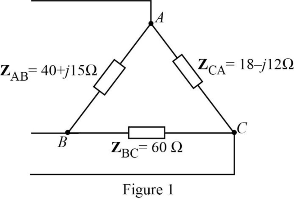
- (a) Calculate the line currents if ZAB = 40 + j15 Ω, ZBC = 60 Ω, ZCA = 18 − jl2 Ω.
- (b) Find the complex power supplied by the source.
a.
Calculate the line currents for the described circuit using PSpice.
Answer to Problem 48P
The value for the line currents
Explanation of Solution
Given data:
The phase voltage is
The transmission line impedance is
The value of the impedances
Formula used:
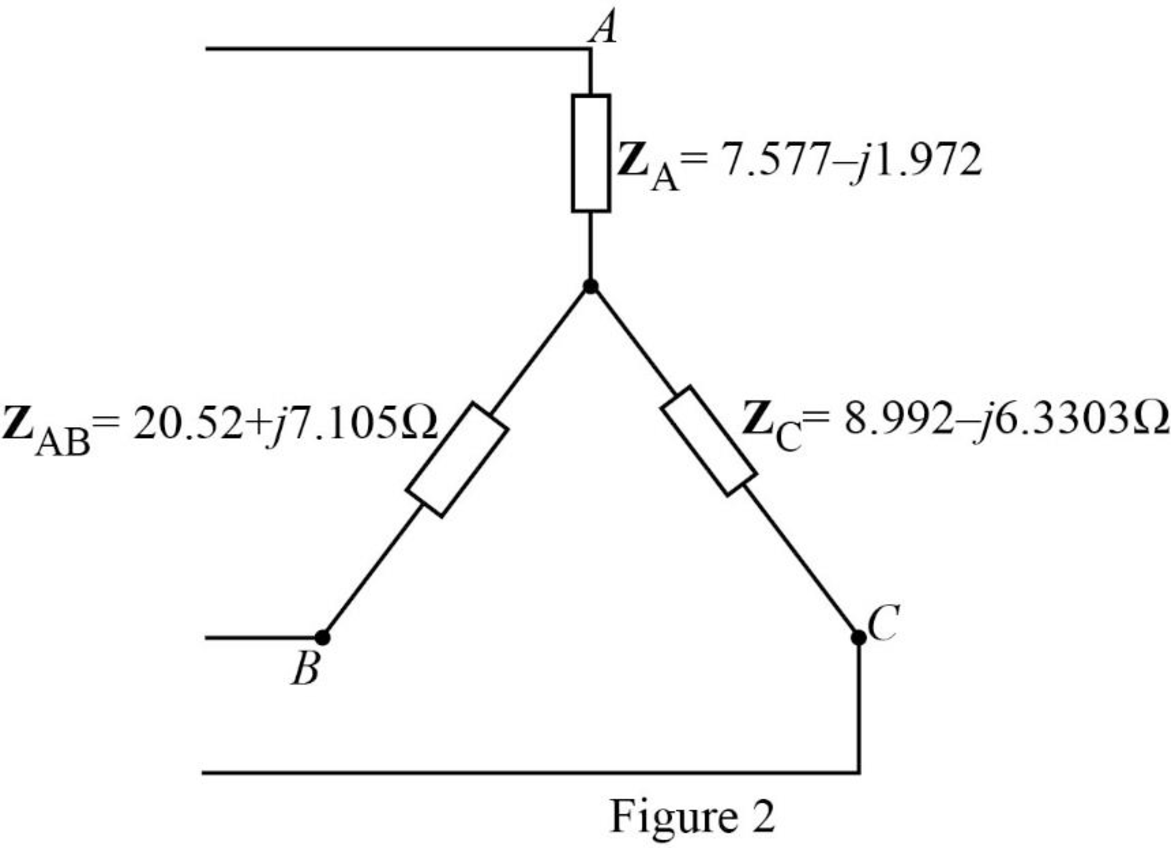
Write the formulae for the conversion of delta connected impedances to star connected impedances.
Here,
Write the expression for reactance of the inductor.
Here,
Write the expression for reactance of the capacitor.
Here,
Calculation:
The given unbalanced delta connected load is shown in Figure 1.
Substitute
Substitute
Substitute
The transformed circuit is shown in Figure 2.
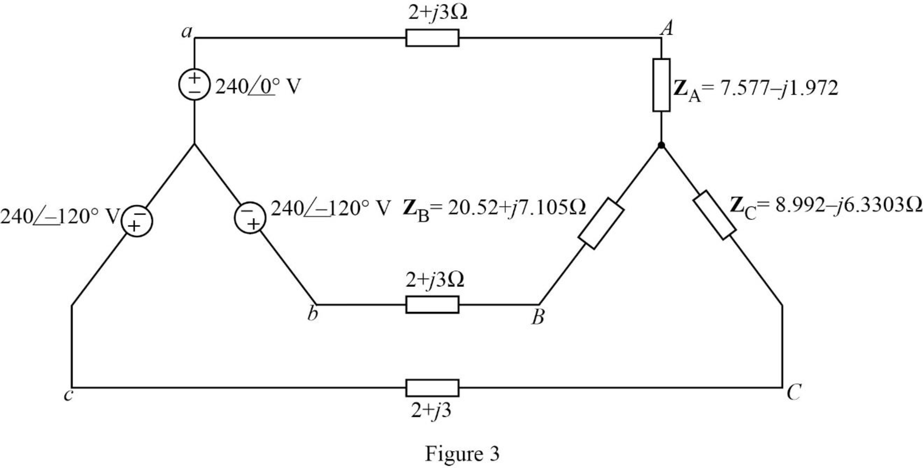
The given balanced wye-connected source supplies the unbalanced delta connected load is shown in Figure 3.
Let us assume that the value of the angular frequency,
Calculate the frequency as follows.
Substitute
Substitute
Substitute
Substitute
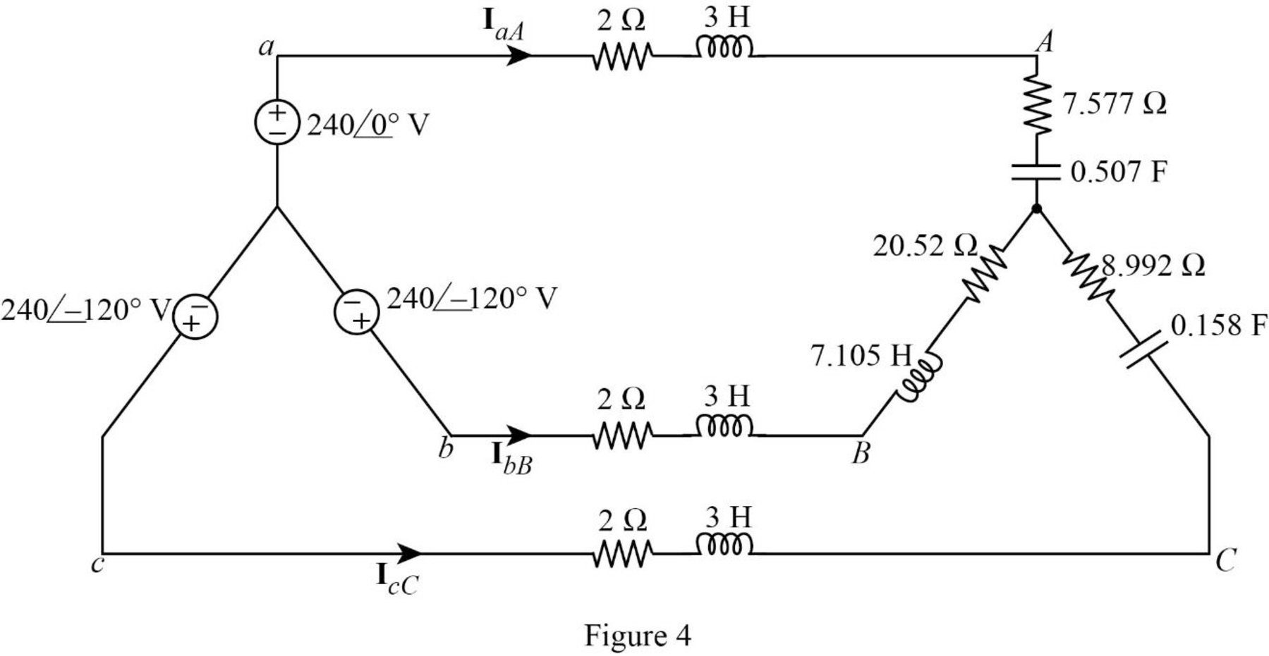
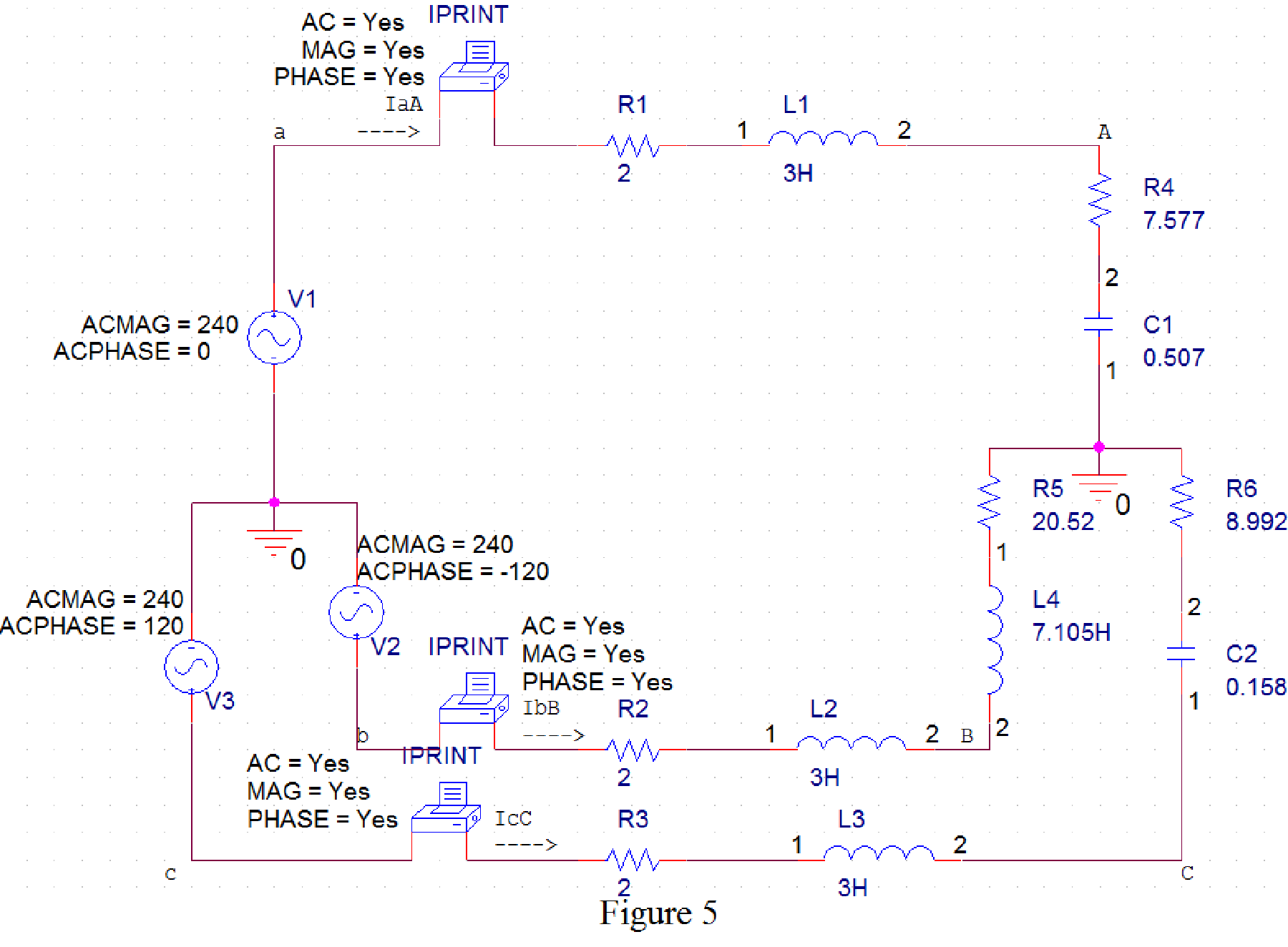
The time domain representation of Figure 3 is shown in Figure 4.
PSpice Simulation:
Draw Figure 4 in PSpice as shown in Figure 5.
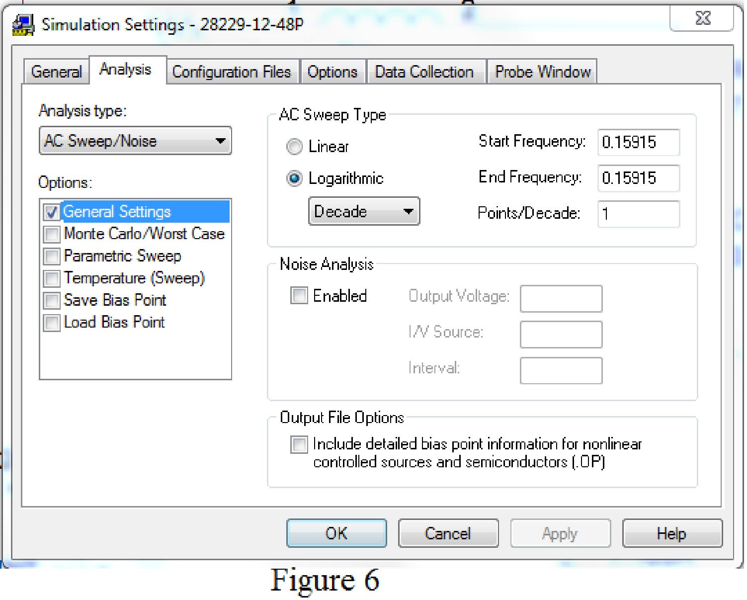
Provide the simulation setting as shown in Figure 6.
The obtained results are given below.
FREQ IM(V_PRINT1) IP(V_PRINT1)
1.592E-01 2.492E+01 -6.124E+00
FREQ IM(V_PRINT2) IP(V_PRINT2)
1.592E-01 9.723E+00 -1.442E+02
FREQ IM(V_PRINT3) IP(V_PRINT3)
1.592E-01 2.094E+01 1.365E+02
The obtained line currents are given below.
Conclusion:
Thus, the value for the line currents
b.
Calculate the total complex power supplied by the source.
Answer to Problem 48P
The total complex power supplied by the source is
Explanation of Solution
Calculation:
Write the expression for complex power delivered by source
Substitute
Write the expression for complex power delivered by source
Substitute
Write the expression for complex power delivered by source
Substitute
Write the expression for total complex power supplied by the source.
Substitute
Conclusion:
Thus, the total complex power supplied by the source is
Want to see more full solutions like this?
Chapter 12 Solutions
Fundamentals of Electric Circuits
Additional Engineering Textbook Solutions
Engineering Electromagnetics
Principles Of Electric Circuits
Electrical Engineering: Principles & Applications (7th Edition)
Microelectronics: Circuit Analysis and Design
Programmable Logic Controllers
Electric machinery fundamentals


- A 3-phase, 50 Hz, overhead transmission line delivers 10 MW at 0·8 p.f. lagging and at 66 The resistance and inductive reactance of the line per phase are 10 W and 20 W respectively while capacitance admittance is 4 × 10- 4 siemen. Calculate : (i)the sending end current (ii) sending end voltage (line-to-line) (iii) sending end power factor (iv) transmission efficiency Use nominal T method.arrow_forwardFind the characteristics of the load at the sending end and the efficiency of a three phase transmission line 160 km long delivering 15 MVA load at 110 kv, 50 Hz and 0.9 power factor (lagging) having inductance 1.356 mH/km per phase, capacitance 0.0085 uF/km per phase and resistance 40 ohms. Use nominal T-method Ans. Is = 70.3 20,8° Amp, Vsa.LD= 117.6 29.2 kV, power factor = 0.9898, n = 95.3%arrow_forwardA 50 Hz, 250 V single phase power line has the following loads placed across it in parallel; 4 kW ata pf of 0. 8 lagging; 6 kVA at a pf of 0.6 lagging; 5 kVA which includes 1.2 kVAR leading. Determinethe overall pf of the system and the capacitance of the capacitor which, if connected across themains restore the power factor to unity.arrow_forward
- A star-connected three-phase balanced power system A transmission line with line impedance Zh It feeds an unbalanced three-phase delta load. Regarding line and load impedances values are given. Zh=2+j, Z1=40+j20, Z2=50-j30 and Z3=25 Accordingly; a)- Calculate IAB and IAC phase currents. b)- Calculate the line currents IAave IBb.arrow_forwardA balanced 3-phase, delta-connected load is connected across a 208 V, balanced 3-phase, ABC source. If it dissipates 10 KW at 60% p.f. lagging, its line current, Ia is ANSWER QUICKLYarrow_forwardA 3-phase, 50-Hz overhead transmission line 100 km long has the following constants : Resistance/km/phase = 0.1 Ω Inductive reactance/km/phase = 0·2 Ω Capacitive susceptance/km/phase = 0·04 × 10− 4 siemens Determine sending end voltage when supplying a balanced load of 10,000 kW at 66 kV, p.f. 0·8 lagging. Use nominal T method . Select one: a. 330 kV b. 52 kV c. None of the above d. 69.5 kVarrow_forward
- Three triphasic loads associated in parallel are powered by a balanced triphasic source: LOAD 1: 250 kVA, Power Factor (PF) = 0,8 (delayed) LOAD 2: 300 kVA, PF = 0,95 (advanced) LOAD 3: 450 kVA, PF = 1 If the line voltage is 13,8 kV, calculate the line current (in ampère). Suppose the line impedance is zero.arrow_forwardDesign a power factor correction circuit with the value of parallel capacitance needed tocorrect a load of 179 kVAR at 0.85 lagging pf to unity pf. Assume that the load issupplied by a 110-V (rms), 60-Hz line.arrow_forwardA 3-phase, 50 Hz, overhead transmission line delivers 10 MW at 0·8 p.f. lagging and at 66 kV. The resistance and inductive reactance of the line per phase are 10 Ω and 20 Ω respectively while capacitance admittance is 4 × 10− 4 siemen. Calculate :(i) the sending end current (ii) sending end voltage (line-to-line)(iii) sending end power factor (iv) transmission efficiencyUse nominal T method.arrow_forward
- The following three parallel-connected three-phase loads are fed by a balanced three-phase source: Load 1: 250 kVA, 0.8 pf lagging Load 2: 300 kVA, 0.95 pf leading Load 3: 450 kVA, unity pf If the line voltage is 13.8 kV, calculate the line current and the power factor of the source. Assume that the line impedance is zero.arrow_forwardS.4) the length of a three-phase power transmission line with a Nominal operating voltage of 69 kV is 16km. The impedance of the transmission line per unit length is 0.125 + j0.4375 ohm/km. From the end of the line, a 56 MW star connected load is fed with a power coefficient of 0.8 back under a 64 kV interphase voltage. If the line head voltage of the transmission line is 69 kV, calculate the capacity and power of the star-connected capacitor to be shunted into the load connected to the end of the line.arrow_forwardq22/ A single phase, 50 Hz, overhead transmission line supplies 1300 kW at 26 kV, 0.65 p.f. lagging. The total resistance and line inductive reactance of the line are 4.75 Ω and 7.75 Ω respectively. Calculate the sending end voltage, voltage regulation, sending end power factor and efficiency of transmissionarrow_forward
 Introductory Circuit Analysis (13th Edition)Electrical EngineeringISBN:9780133923605Author:Robert L. BoylestadPublisher:PEARSON
 Delmar's Standard Textbook Of ElectricityElectrical EngineeringISBN:9781337900348Author:Stephen L. HermanPublisher:Cengage Learning
 Programmable Logic ControllersElectrical EngineeringISBN:9780073373843Author:Frank D. PetruzellaPublisher:McGraw-Hill Education
 Fundamentals of Electric CircuitsElectrical EngineeringISBN:9780078028229Author:Charles K Alexander, Matthew SadikuPublisher:McGraw-Hill Education
 Electric Circuits. (11th Edition)Electrical EngineeringISBN:9780134746968Author:James W. Nilsson, Susan RiedelPublisher:PEARSON
 Engineering ElectromagneticsElectrical EngineeringISBN:9780078028151Author:Hayt, William H. (william Hart), Jr, BUCK, John A.Publisher:Mcgraw-hill Education,