Concept explainers
(a)
Draw the influence line for the positive moment at section B using moment distribution method.
(a)
Explanation of Solution
Influence line for the moment at support B.
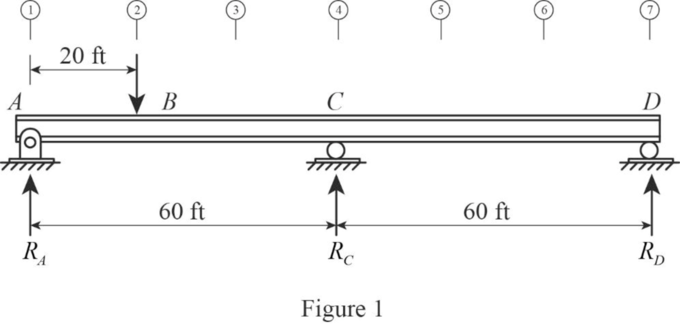
Influence lines will be constructed by placing the unit load at every 20 ft interval from A along the span of the beam. The points are indicated by the circled numbers.
To establish the influence line ordinate at the left end (point 1), the unit load is placed on the beam directly over support A. Since the entire load passes directly into the support, the beam is unstressed. Therefore,
Similarly, if the unit load is moved at C and D,
Case 1:
Apply unit load at 20 ft from A. (point 2).
Draw the beam with points of applying unit load at B (point 2) as in Figure 1.
Refer Figure 1.
Find the fixed end moment at each end of the member CD as follows;
Find the fixed end moment at each end of the member CA as follows;
Find the distribution factor.
Show the computation of distribution factor as in Table 1.
| Joints | Member | Stiffness, K | ||
| C | CA | |||
| CD |
Show the moment distribution computations as in Table 2.
| Joint | A | C | D | ||
| Member | AC | CA | CD | DC | |
| DF | 0.5 | 0.5 | |||
| FEM | ‑8.89 | 4.44 | 0 | 0 | |
| Released moment | +8.89 | 0 | 0 | 0 | |
| COM | 0 | 4.44 | 0 | ||
| Total | 0 | 8.88 | 0 | 0 | |
| DEM | ‑4.44 | ‑4.44 | |||
| COM | |||||
| Final | 0 | 4.44 | ‑4.44 | 0 | |
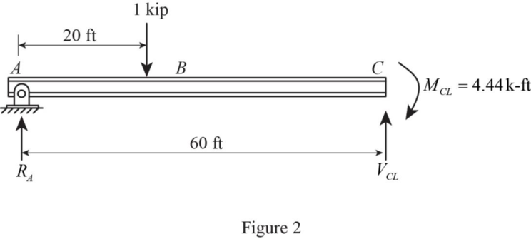
Find the reaction at A using section AC.
Draw the free body diagram of section AC as in Figure 2.
Refer Figure 1.
Find the reaction at A.
Consider moment at C
Find the moment at B.
Consider moment at B
Thus, the influence line ordinate of moment at B when 1 kip applied at B is 11.86.
Case 2:
Apply unit load at 20 ft from C. (point 5).
Draw the beam with points of applying at point 5 as in Figure 3.
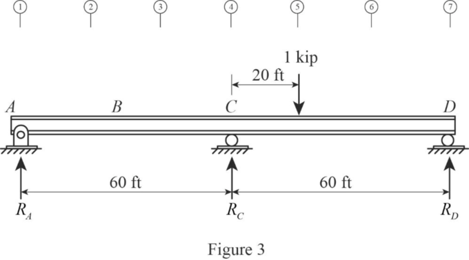
Refer Figure 3.
Find the fixed end moment at each end of the member CD as follows;
Find the fixed end moment at each end of the member DC as follows;
Show the moment distribution computations as in Table 3.
| Joint | A | C | D | ||
| Member | AC | CA | CD | DC | |
| DF | 0.5 | 0.5 | |||
| FEM | 0 | 0 | ‑8.89 | 4.440 | |
| Released moment | 0 | 0 | 0 | ‑4.44 | |
| COM | 0 | 0 | ‑2.22 | ||
| Total | 0 | 0 | ‑11.11 | 0 | |
| DEM | +5.56 | +5.56 | |||
| COM | |||||
| Final | 0 | 5.56 | ‑5.56 | 0 | |
Find the reaction at A using section AC.
Draw the free body diagram of section AC as in Figure 4.
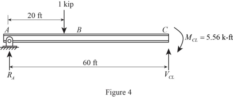
Refer Figure 4.
Find the reaction at A.
Consider moment at C
Find the moment at B.
Consider moment at B
Thus, the influence line ordinate of moment at B when 1 kip applied at point 5 is ‑1.876.
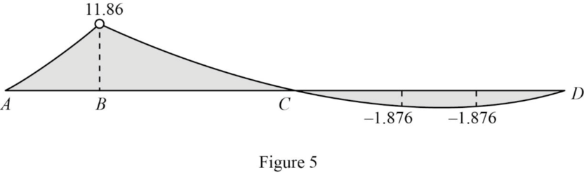
Similarly calculate the influence line ordinate by applying the points 3 and 5 and tabulate the values as in Table 4.
| Apply 1 k at point | Influence line ordinate of moment at B. |
| 1 | 0 |
| 2 | 11.86 |
| 4 | 0 |
| 5 | ‑1.876 |
| 6 | ‑1.876 |
| 7 | 0 |
Draw the influence line diagram of influence line ordinate of moment at B using Table 4 as in Figure 5.
(b)
Find the maximum moment at B for the given loading condition.
(b)
Answer to Problem 53P
The maximum moment at B for the given loading condition is
Explanation of Solution
Consider the uniformly distributed load of 2 kips/ft act on the span AC only and the concentrated live load of 20 kips act at B.
Draw the free body diagram of the beam for the given loading as in Figure 6.
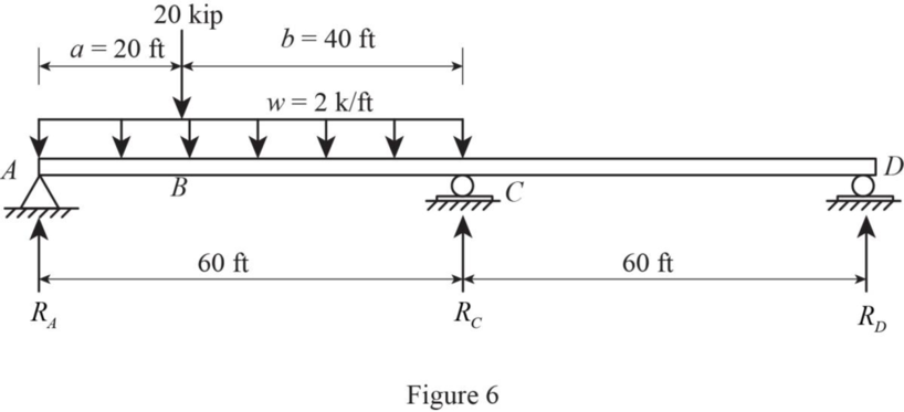
Refer Figure 6.
Find the fixed end moment at each end of the member AC as follows;
Find the fixed end moment at each end of the member CA as follows;
Show the moment distribution computations as in Table 5.
| Joint | A | C | D | ||
| Member | AC | CA | CD | DC | |
| DF | 0.5 | 0.5 | |||
| FEM | ‑777.78 | 688.89 | 0 | 0 | |
| Released moment | +777.78 | 00 | 0 | 0 | |
| COM | 388.89 | ||||
| Total | 0 | 1,077.78 | 0 | 0 | |
| DEM | ‑538.89 | ‑538.89 | |||
| COM | |||||
| Final | 0 | 538.89 | ‑538.89 | 0 | |
Find the reaction at A using section AC.
Draw the free body diagram of section AC as in Figure 7.
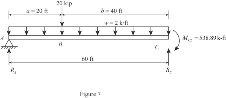
Refer Figure 7.
Find the reaction at A.
Consider moment at C
Find the moment at B.
Consider moment at B
Therefore, the maximum moment at B for the given loading condition is
(c)
Find the maximum moment at B due to wheel loads using moment distribution method.
(c)
Answer to Problem 53P
The maximum moment at B due to wheel loads using moment distribution method is
Explanation of Solution
The maximum moment at B is produced when wheel load is placed at B.
Draw the free body diagram of the beam for the wheel loading as in Figure 8.
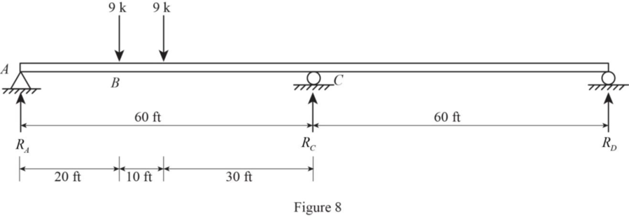
Refer Figure 8.
Find the fixed end moment at each end of the member AC as follows;
Find the fixed end moment at each end of the member CA as follows;
Show the moment distribution computations as in Table 6.
| Joint | A | C | D | ||
| Member | AC | CA | CD | DC | |
| DF | 0.5 | 0.5 | |||
| FEM | ‑147.5 | 107.5 | 0 | 0 | |
| Released moment | +147.5 | 0 | 0 | 0 | |
| COM | 73.75 | ||||
| Total | 0 | 181.25 | 0 | 0 | |
| DEM | ‑90.63 | 90.63 | |||
| COM | |||||
| Final | 0 | ‑90.63 | 90.63 | 0 | |
Find the reaction at A using section AC.
Draw the free body diagram of section AC as in Figure 9.
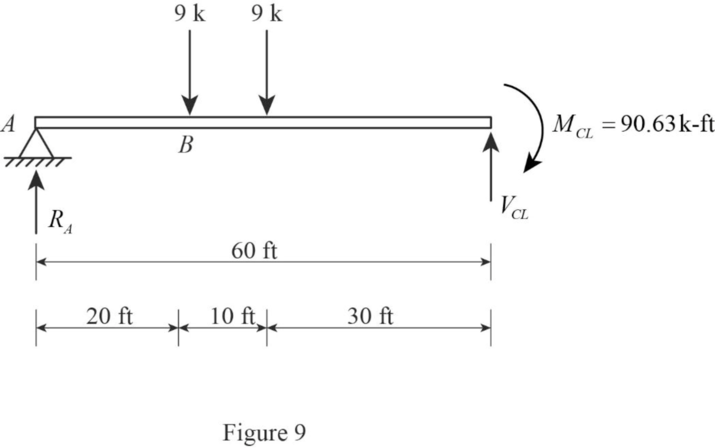
Refer Figure 7.
Find the reaction at A.
Consider moment at C
Find the moment at B.
Consider moment at B
Therefore, the maximum moment at B for the given loading condition is
Want to see more full solutions like this?
Chapter 12 Solutions
Fundamentals of Structural Analysis


 Structural Analysis (10th Edition)Civil EngineeringISBN:9780134610672Author:Russell C. HibbelerPublisher:PEARSON
 Principles of Foundation Engineering (MindTap Cou...Civil EngineeringISBN:9781337705028Author:Braja M. Das, Nagaratnam SivakuganPublisher:Cengage Learning
 Fundamentals of Structural AnalysisCivil EngineeringISBN:9780073398006Author:Kenneth M. Leet Emeritus, Chia-Ming Uang, Joel LanningPublisher:McGraw-Hill Education
 Traffic and Highway EngineeringCivil EngineeringISBN:9781305156241Author:Garber, Nicholas J.Publisher:Cengage Learning